Bluetooth Controlled LED Display
Check out the project on Github! Go to GitHub >
Background
I love red-green-blue light-emitting diodes (RGB LEDs). These little electronic components produce light ranging from red to green to blue to any other color in between. There is something about the vast amount of things that can be done with such a simple component that makes RGB LEDs so intriguing to me.
My first real encounter with RGB LEDs was in 2014 during my junior year, while participating on the local robotics team that I helped start as a freshman, Ctrl-Z (team4096.org). In the previous year, Ctrl-Z started putting LEDs on its robot to help draw attention to it during competitions. There were two colors of LED strips on the robot to match the team’s colors: orange and blue. Operation was simple enough for the inexperienced team - while the robot’s Frisbee thrower was on, the blue LED strip was lit, and while it was off, the orange strip was lit. Many people enjoyed these super bright LEDs, but they lacked creativity. The team decided that the next year, more advanced LEDs would be used.
As a junior, I realized that my other extracurricular activities were filling my time, thus pushing me away from Ctrl-Z. I felt that continuing with the team I helped start was critical, so I tasked myself with solely helping the team make the LEDs on the robot better. This is when I discovered NeoPixels. NeoPixels are individually addressable, super bright, RGB LEDs. This means that each “pixel,” or RGB LED, in a strip of NeoPixels can be controlled independently of the other LEDs to produce bright colorful light (see picture on right). Since Ctrl-Z started using NeoPixels two years ago, each robot has been covered in them to light up the competition field and draw attention to the team. After graduating from high school, I wanted to build one final LED project that would combine all my knowledge I learned from participating on Ctrl-Z. Looking online for LEDs to buy for my final project, I discovered that NeoPixels not only are sold in strips, but also in panels. I ended up purchasing a 16x16 NeoPixel panel to use for my project. Coincidentally, just after ordering the panel, I discovered a project online that used the same panel I ordered. I then knew what I wanted to make: an LED display. The goal of the project was to store patterns and images on a SD card and then transfer the data from the SD card to the LED display.
Hardware
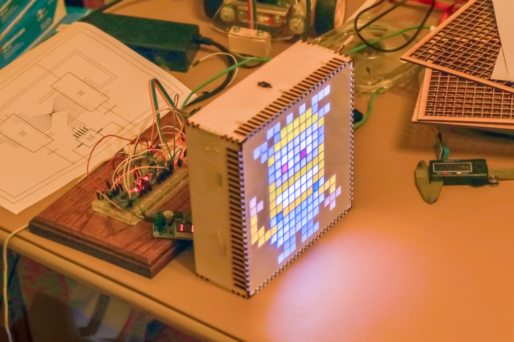
The part of the LED display that shows patterns and images is made of 256 NeoPixels arranged in a square grid. A NeoPixel is actually an Adafruit branded name for the WS2812B 5050 RGB LED. Each “pixel” has a controller chip in the LED housing that controls the output. The advantage of using the WS2812B chip is that only one signal wire is required for programmatic control of any reasonable number of LEDs, leaving other I/O pins available for different things. Adafruit provides a very easy-to-use library to interface with NeoPixels.
There are two major drawbacks of the seemingly magical NeoPixel: the memory consumption for a microcontroller scales directly with the number of pixels controlled and while pushing data to the controller chips, software interrupts must be turned off. Each pixel actually contained a red, green, and blue LED, causing the software to store each of the three LED values separately. The Adafruit library packs these color values into one 32-bit unsigned integer. This means that the buffer for 256 NeoPixels is 1024 bytes, or 1 kilobyte, or half of the available 2 kilobytes microcontroller RAM. If there are other memory intensive parts to the program running the NeoPixels, the microcontroller might run out of memory and crash. The other drawback involves the precise timing needed for pushing data to a NeoPixel. An interrupt is a signal emitted to a processor by hardware or software indicating an event that needs immediate attention. These interrupts break the flow of a program, so if an interrupt happened to go off while the NeoPixels were receiving data, it would cause the NeoPixels to receive corrupted data. To prevent this, the Adafruit library turns off interrupts while pushing data to the NeoPixels.
The microcontroller does not have enough memory to store more than one or two full frames needed to update the NeoPixel matrix. Because the LED display needed the ability to be fully functional with many images, an external memory system was needed. A SD card was chosen for data storage because of its large storage size and ease of use with microcontrollers. The frame data are stored as bytes on a SD card, which is then read into software and pushed to the LED panel.
All of these individual components require software that takes memory. As noted earlier, the buffer for 256 NeoPixels alone is half of the available RAM on an Arduino Uno. Moreover, the default Arduino library for SD cards is also large; when compiled, it’s 13,690 bytes, which is over half of the Uno’s RAM. For all of these systems to function properly, more RAM was needed. This led to a significant hardware design for this project: two Arduino microcontrollers communicating with each other via an eight-bit parallel bus. One Arduino controls the SD card reader/writer and the other Arduino controls the actual NeoPixel panel. This keeps the memory requirements within the limits of each Arduino microcontroller.
Software
The crux of the LED display’s existence is the parallel bus that links the two Arduinos together. Without fast, error-free communication, the display would be unusable.
To achieve this type of communication, a unidirectional eight-bit parallel bus is used. This means that there are eight signal wires going between the two Arduinos to pass complete bytes across in one operation. Two more wires are required for relaying the status if the data are received or sent.
To send one byte, or eight bits, from the SD card Arduino to the LED Arduino, many steps are required. First, the software must understand what a byte actually is. A byte contains eight bits which can either be true or false, like a boolean data type. A byte has a range of 0 to 255. For example, the decimal number 255 can be written in binary as 11111111. The software running on the Arduino takes the binary bits and writes them to the signal wires.
Using the previous example, if 255 is transmitted, all the signal wires would be set to HIGH by the SD card Arduino. The SD card Arduino then sets the BYTE_READY signal wire to HIGH to signify that the LED Arduino can now read the data. When the LED Arduino detects that the BYTE_READY wire is HIGH, it reads the bits off of the signal wires and constructs the binary number. After it finishes reading the bits, it sets the BYTE_RECEIVED wire HIGH. The SD card Arduino detects this and resets the BYTE_READY bit to LOW. The LED Controller then detects the LOW BYTE_READY and sets the BYTE_RECEIVED back to low. The transmission process is now ready to begin again. The use of the BYTE_RECEIVED and BYTE_READY signal wires allows the Arduinos the ability to perform “handshaking” to successfully transfer a byte very fast and without errors.
The first attempt at storing colors involved using 8-bit color. This means that all color data can be packed into one byte, or eight bits. The red values use three bits, the blue values use three bits, and the green values use just two bits. There are both pros and cons to this method: a pro is that only one byte is needed per NeoPixel, leading to faster update rates, while some cons include a color palette that is limited to 256 colors, and the inability to represent gray scale in software. This was not going to satisfy the needs of the project, so a different data storage method was needed.
The final method for transmitting data from Arduino to Arduino uses four-byte chunks for each NeoPixel. The first byte contains command data about what to do with the following three bytes. The final three bytes store values for each color channel. This allows for 224 different color combinations, or 16.8 million different colors. The use of a separate command byte enables the SD card Arduino to easily instruct the LED Arduino to perform actions like clearing its buffer, pushing data out to the NeoPixel panel, and filling the panel with one color.
There are several drawbacks that come from the current software architecture. Data for each of the 256 NeoPixels must sent between Arduinos every time the screen updates, so on average it takes approximately 1024 bytes to update the screen. This is rather inefficient, leading to a maximum refresh rate of about seven frames per second.
Summary
The LED display taught me many things, even though it was intended to combine my previous knowledge to form something exciting. I learned about parallel buses and the handshaking methods for successfully transferring data between processors at high speeds. I also learned about color management and the different ways color can be represented in memory.
If anything, this project has made me much more appreciative of high resolution displays that many people take for granted daily, like televisions and computer monitors.
Future
In the future, I plan to continue to work on the LED display. There are many modifications and improvements that would make the LED display even better. I plan on adding bluetooth support and writing a custom Android app so that the SD card can be easily updated from a mobile device. The NeoPixel panel gets very hot at full brightness, so for safety, I plan on adding a fan and temperature sensor so the LED Arduino can constantly monitor the panel temperature and regulate it as needed.
The communication between Arduinos will also be improved. I plan on modifying the protocol so that the SD card Arduino can tell the LED Arduino which NeoPixels to update. Animations such as a waving hand would benefit greatly from this optimization because only a few pixels update between frames; playback would be much smoother. In the end, I really want the communication to be fast enough so that I can stream a camera feed from the mobile app and have it update in real time on the LED display.
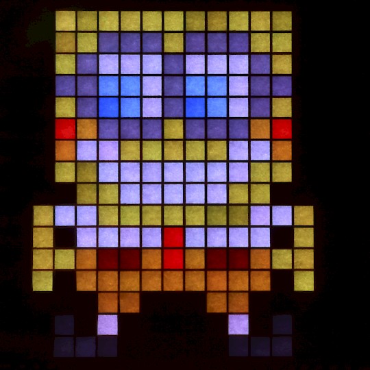
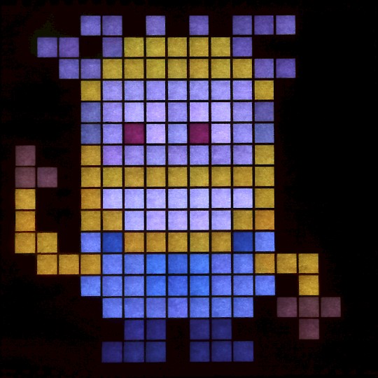
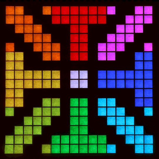
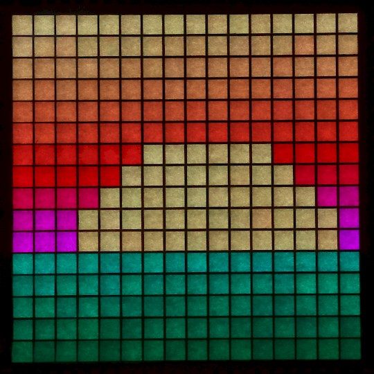
Examples