4-H Electronics Project 2006
This post is one of a six part series documenting and archiving Nathan’s electronic projects created during his years participating in 4-H. To be clear, this project was done many years ago. During the winter months of 2017-2018, Nathan decided to archive his past projects as a way to remember and share them, hoping to inspire other beginning electronic hobbyists.
Summary
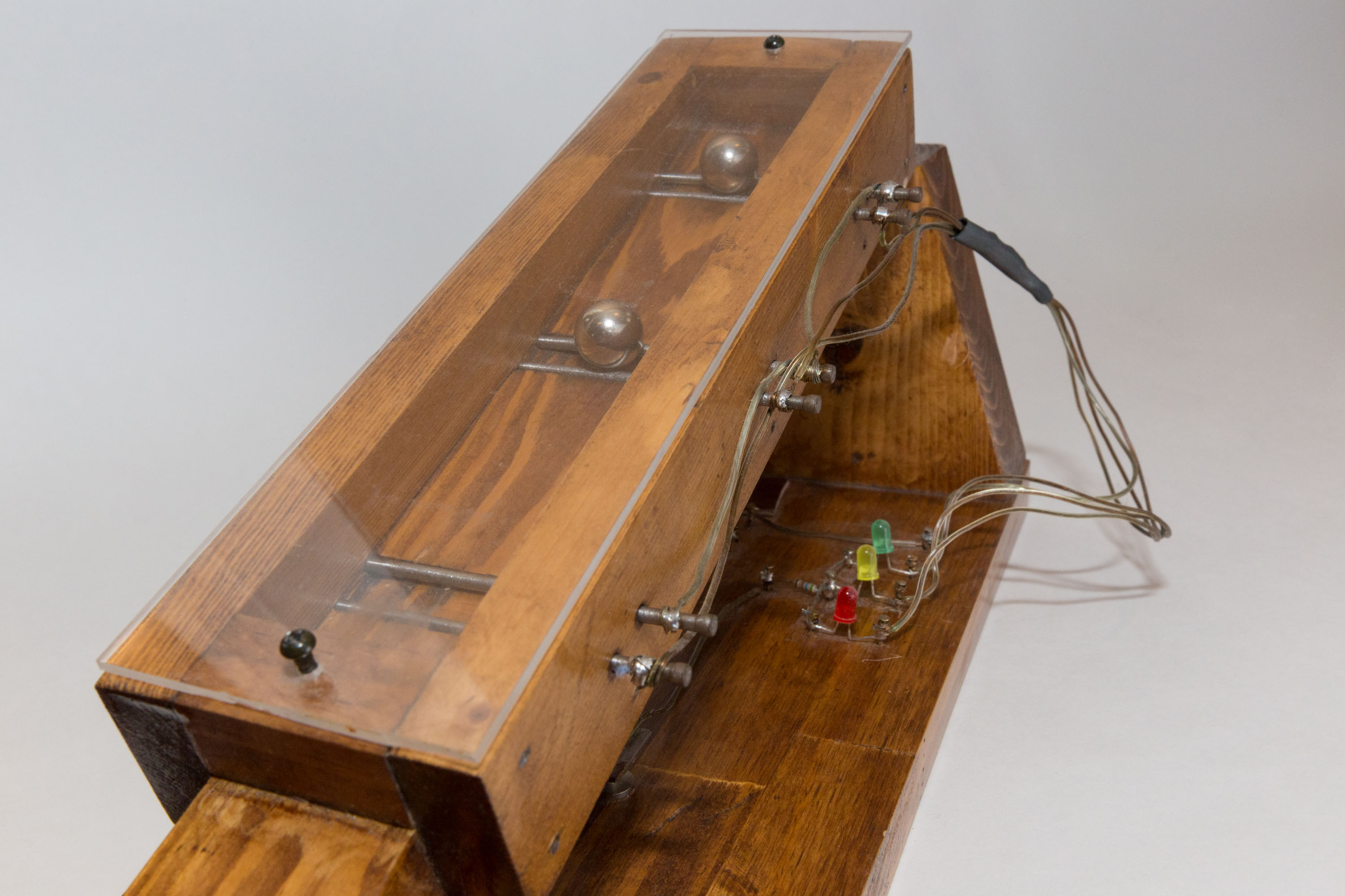
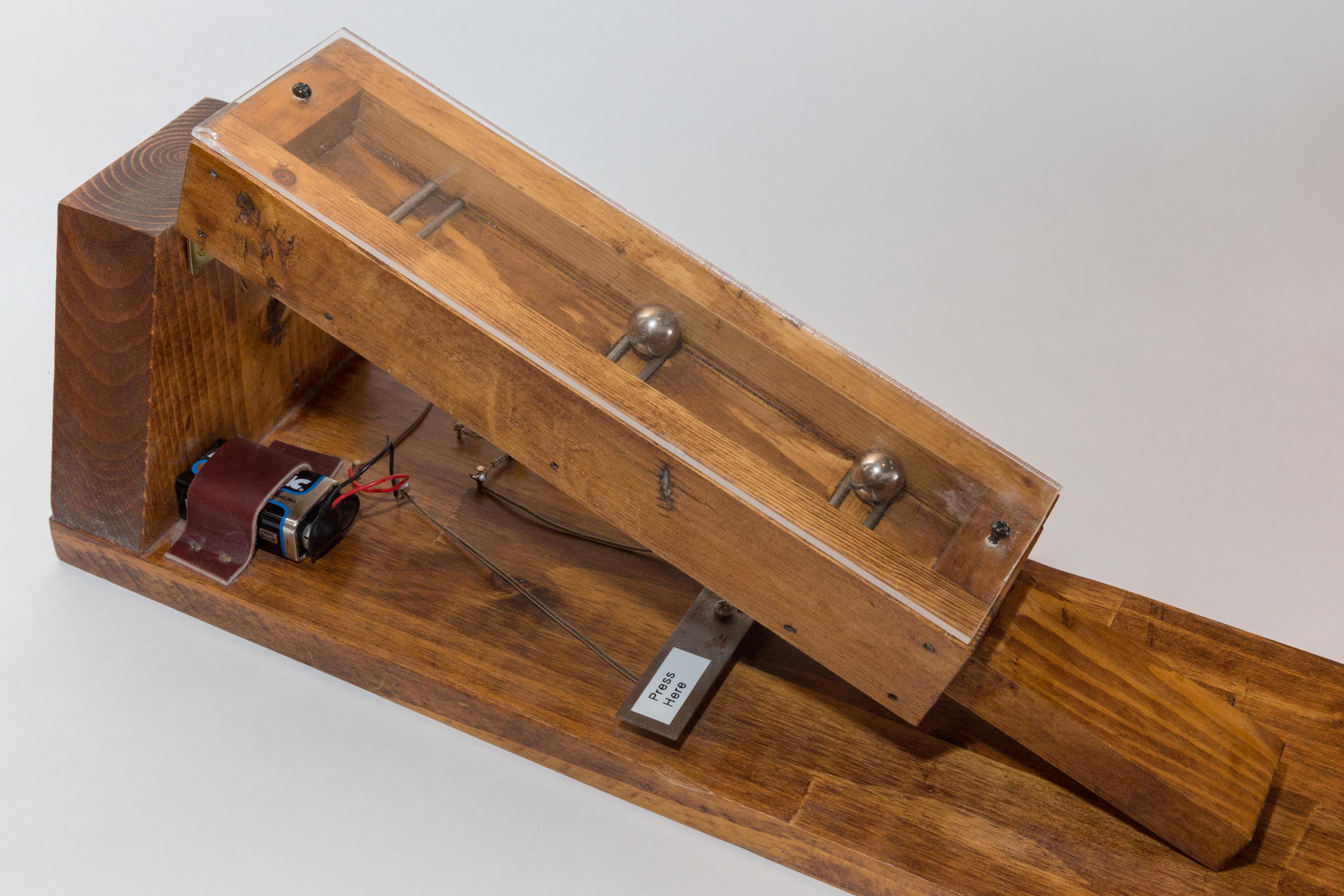
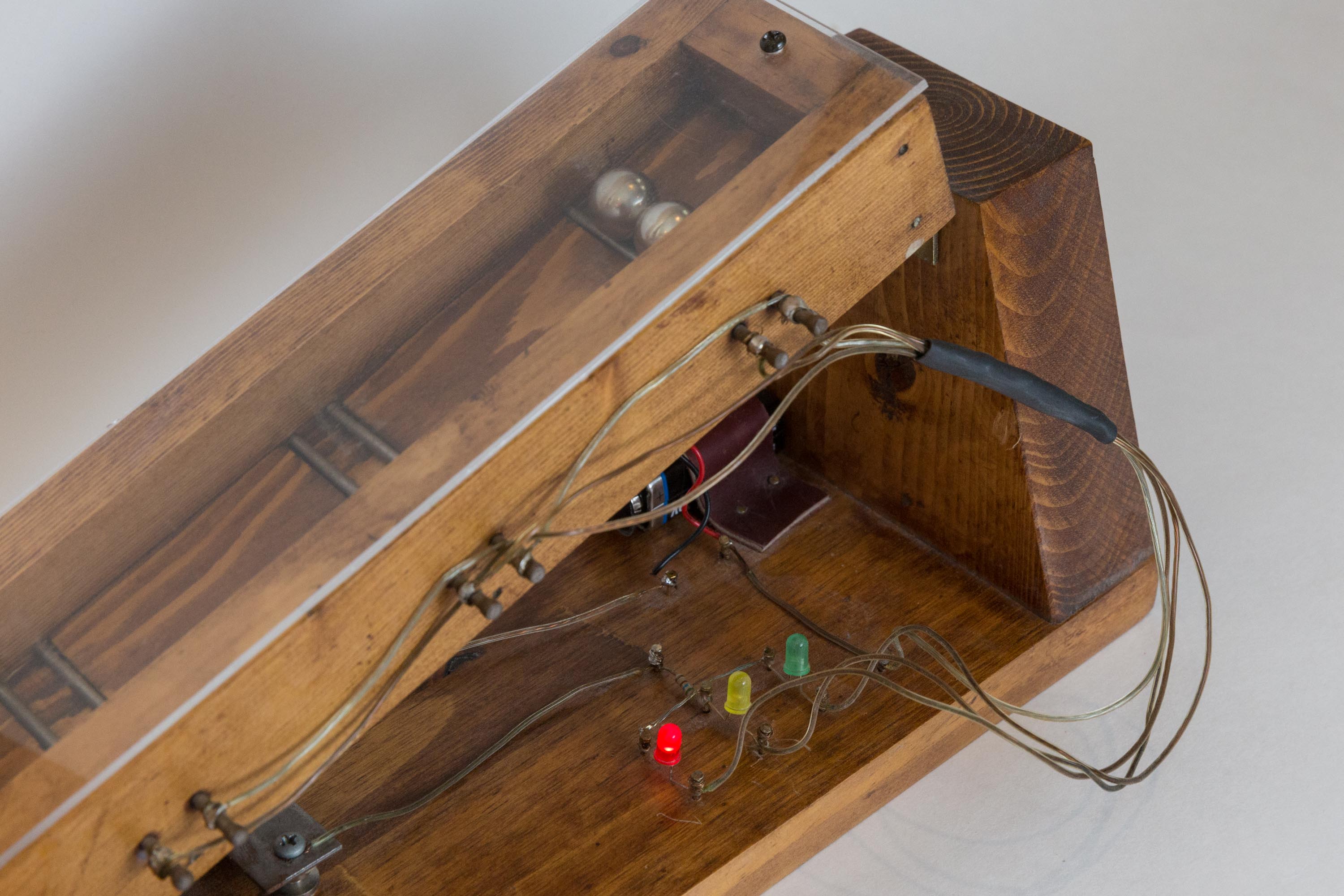
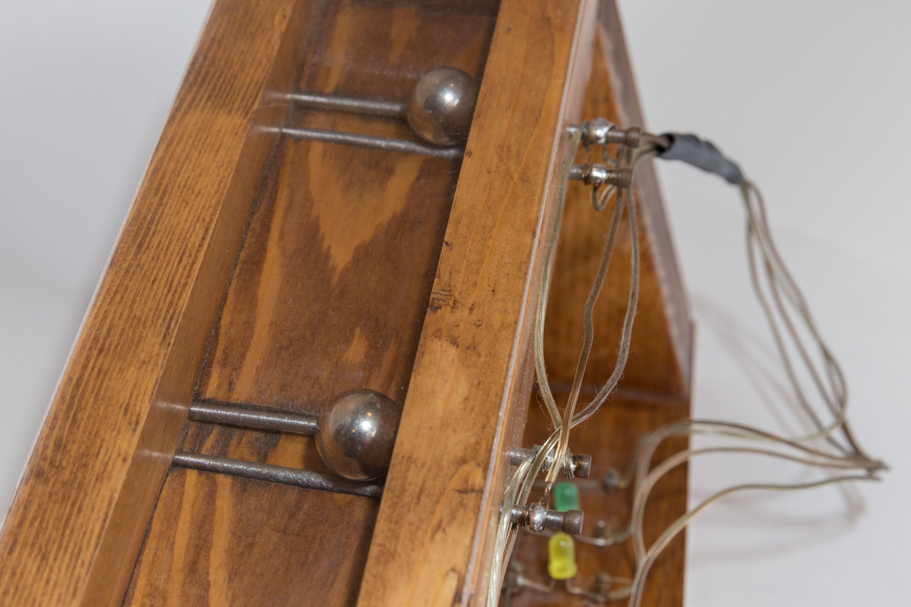
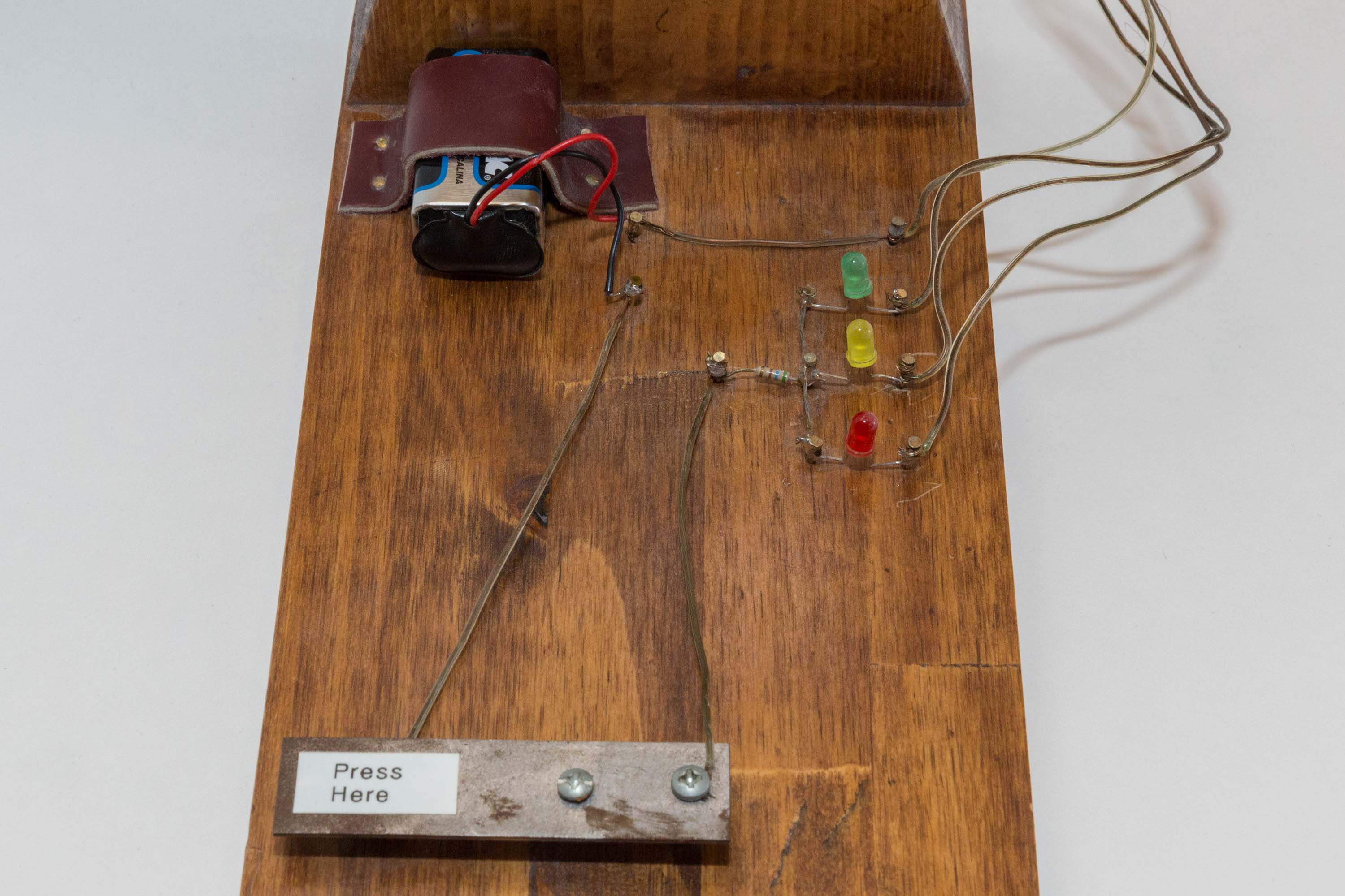
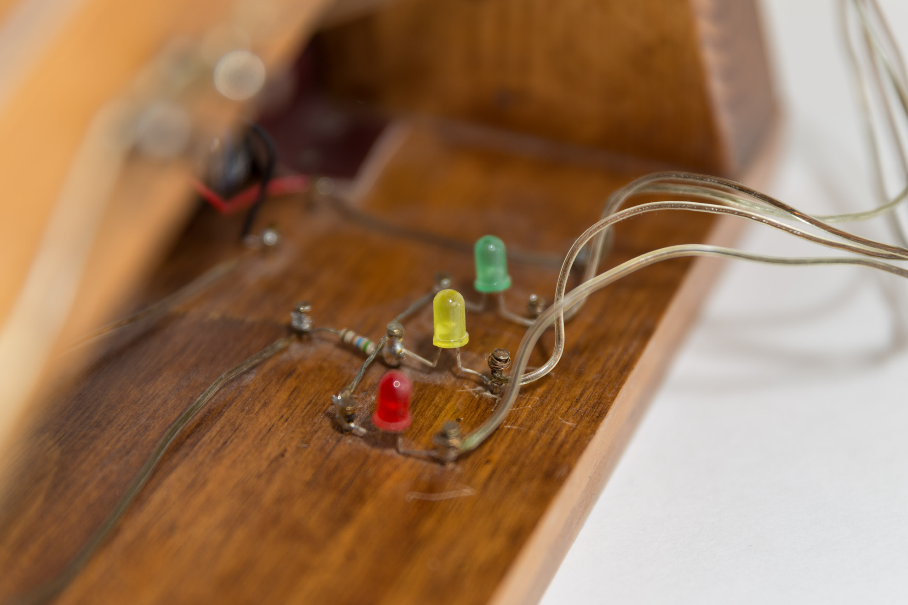
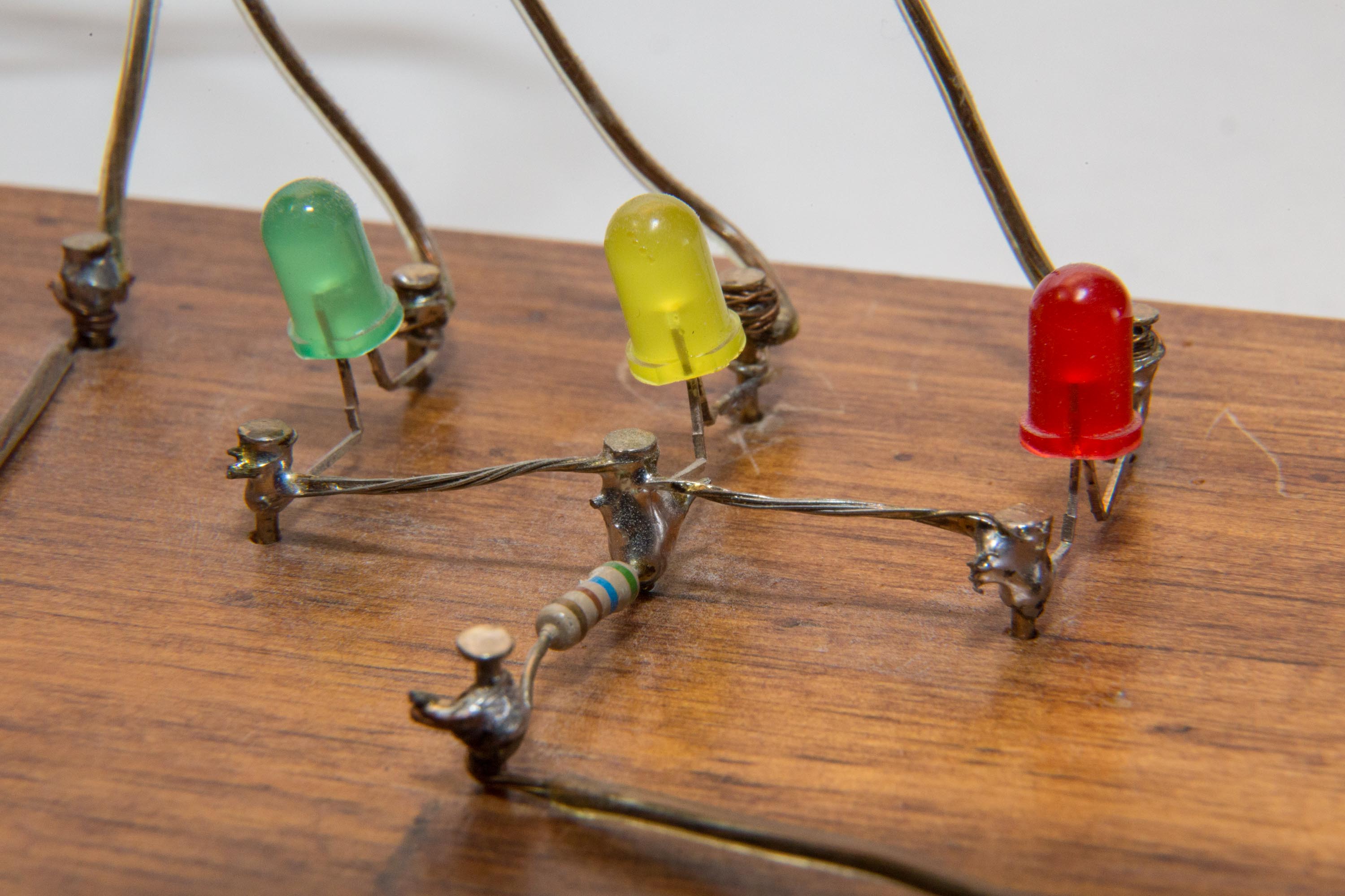
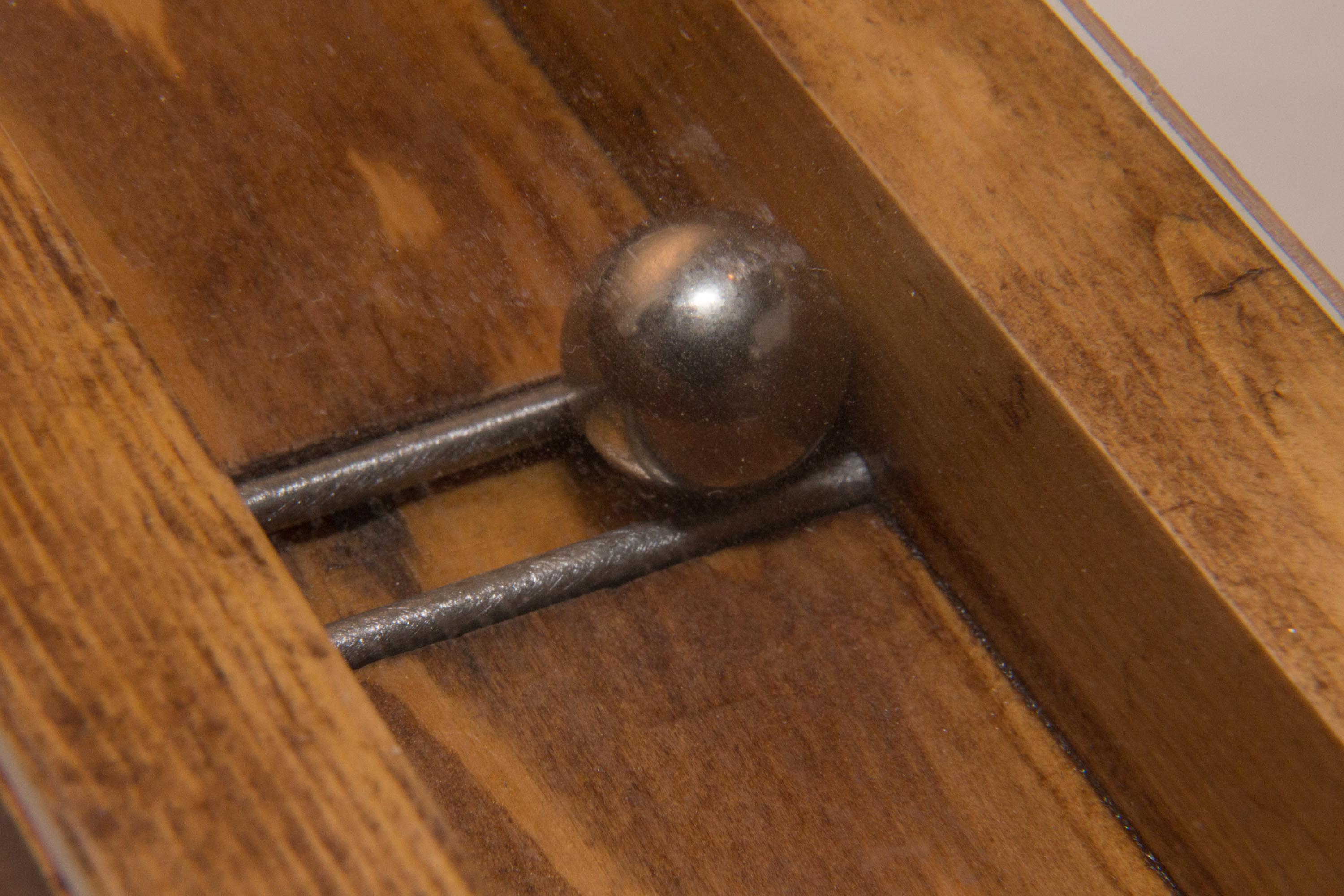
This project is a simple game: the goal is to illuminate LEDs by positioning metal balls on channels created by two horizontal nails on the game surface. The angle of the hinged game surface is changeable by raising or lowing its handle. Multiple LEDs can be illuminated at one time, since there are two balls in use. The lever labeled “Press Here” must be pushed to complete the circuit and play the game.
Below you can see the electrical schematic that this project implements. It should be apparent that this is a very simple project… Good for a nine-year-old. ;)
Schematic
View the PDF version: click here.

Original 4-H Report
The text written below is directly from Nathan’s report given with this project at the 4-H Exposition of 2006, when Nathan was nine years old.
The way I made this game is my dad cut the wood pieces. I sanded all the pieces and nailed and glued them together. Then I stained them and put polyurethane on the wood pieces. After they dried, I hammered the nails into place for the wires. Next I stripped the plastic from around the wires and wrapped the wire around the nails. My dad helped me solder on the wires to the nails; he held the soldering iron while I used the solder. There are 3 simple switches connected to the LEDs. The balls complete the circuit. I learned that LEDs can”burn” out if they have too much voltage through them so I needed to add a resistor.
To play my game, you should press the “press here” switch, and try to get two LEDs on by positioning the balls between two different sets of nails.
Pictures