4-H Electronics Project 2007
This post is one of a six part series documenting and archiving Nathan’s electronic projects created during his years participating in 4-H. To be clear, this project was done many years ago. During the winter months of 2017-2018, Nathan decided to archive his past projects as a way to remember and share them, hoping to inspire other beginning electronic hobbyists.
Summary
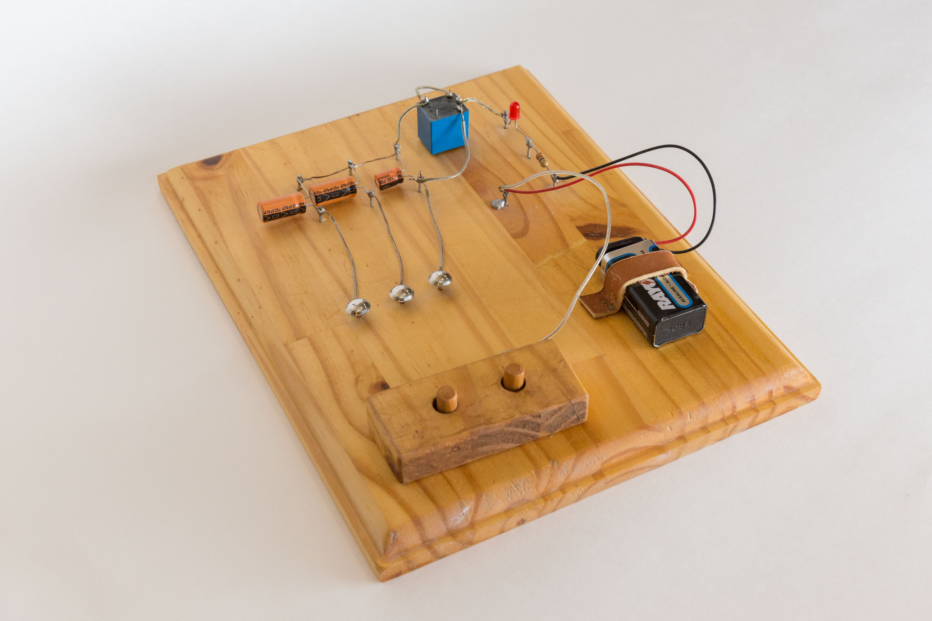
This project demonstrates some properties of capacitors and relays. It uses capacitor charging to act as a timer for triggering a relay, which in turn powers a LED. The series combination of these elements makes the LED flash on and off at a frequency determined by the amount of capacitance.
To really highlight the effect of capacitance versus oscillation frequency, this project uses a parallel capacitor ladder that lets the user change the number of parallel capacitors. Since the effective capacitance of parallel capacitors simply adds, this configuration enables the user to sum the individual capacitance together to slow the LED oscillation frequency.
$$ C_\text{parallel} = C_1 + C_2 + … + C_N $$
Circuit Analysis
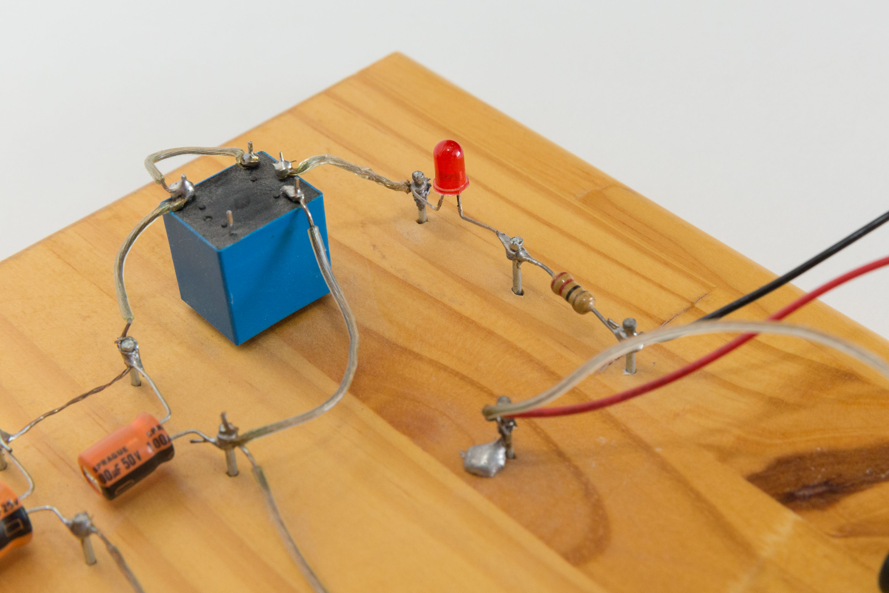
Initially, the capacitors are discharged and the relay is connected as shown in the schematic below. When the user completes the circuit, the connected capacitors start charging, with current flowing through the resistor, LED, and relay. Once the capacitors charge to the relay activation voltage, the electromagnet pulls the relay switch, disconnecting the LED. The capacitors then discharge through the resistance in the relay coil until the switch disengages. This starts the whole cycle over again.
Schematic
View the PDF version: click here.

Original 4-H Report
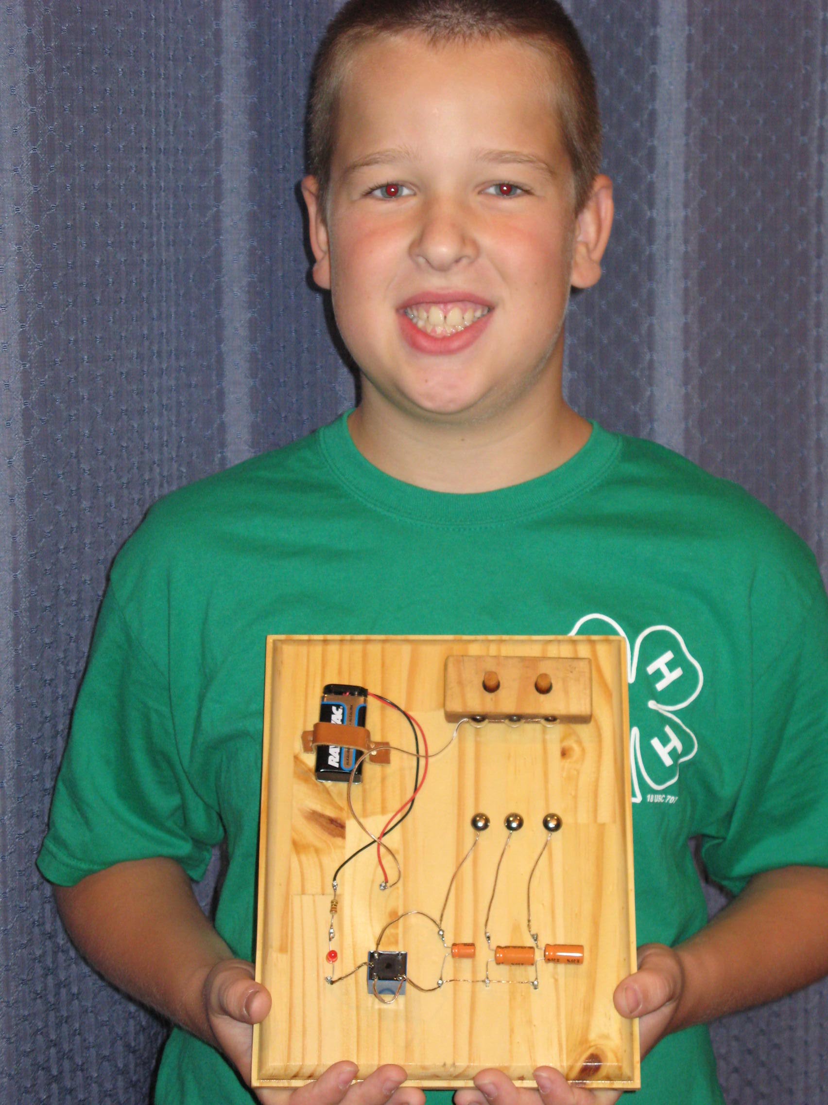
The text written below is directly from Nathan’s report given with this project at the 4-H Exposition of 2007, when Nathan was ten years old.
I like things that make noise and that have flashing lights, so this year I learned about batteries, electro-magnets, and capacitors. I learned that capacitors behave a little like batteries, but they charge and discharge very fast. I also learned that when you wrap wire around a nail and connect it to a battery it turns into an electro-magnet. We searched on the internet to find a circuit so I could use what I learned to make a fun 4-H project. The circuit was for a buzzer, but we changed it to flash a light instead.
We went to Radio Shack and bought a relay. My dad told me a relay is a switch that is controlled by a electro-magnet. The switch is normally on (closed) but when you connect the battery to the relay, the electro-magnet charges and turns the switch off (open). We also bought a light (LED and resistor) and several capacitors that I needed to make the circuit.
The way the circuit works is the energy flows through the capacitors which charges them. Then the energy is free to run, so it goes right on through the relay, since the electro-magnet hasn’t been charged yet, and the switch is still set to on. Then it goes on to the LED (light) and turns it on. Now the battery sends more energy which tries to go through the capacitors, but can’t because they are now full, which blocks the energy. Now the energy flows through the electro-magnet which brings the switch down (open or off) and turns off the LED (light). The electro-magnet now gets its energy from the capacitors until they run out of charge. When the capacitors are empty the electro-magnet turns off and resets the switch back to closed or on. This resets the circuit to its original condition so it can start over. It continues doing this while the circuit is complete. If you didn’t understand that then you might understand this. My project is basically an oscillating circuit that turns on and off a light (LED) pretty fast.
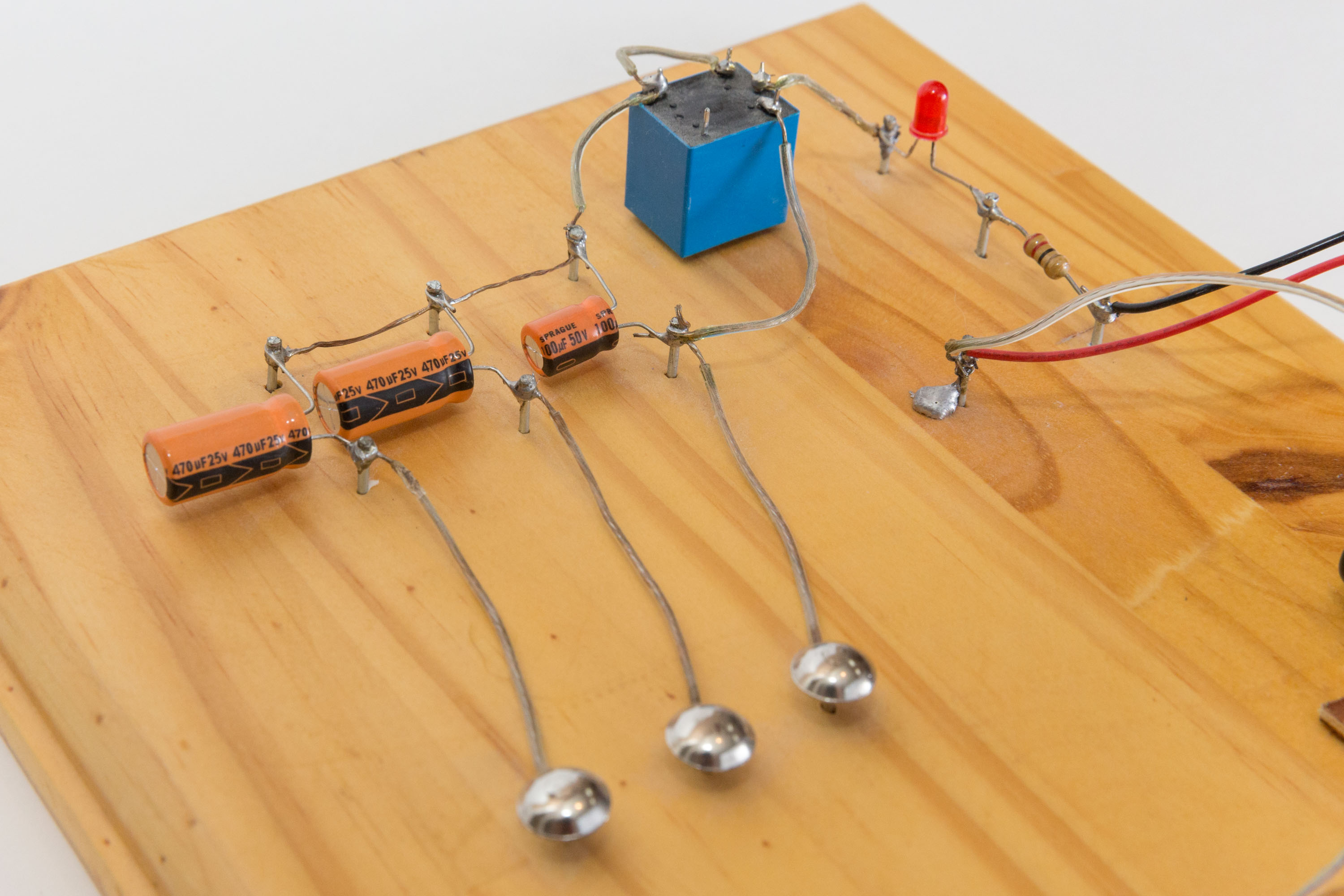
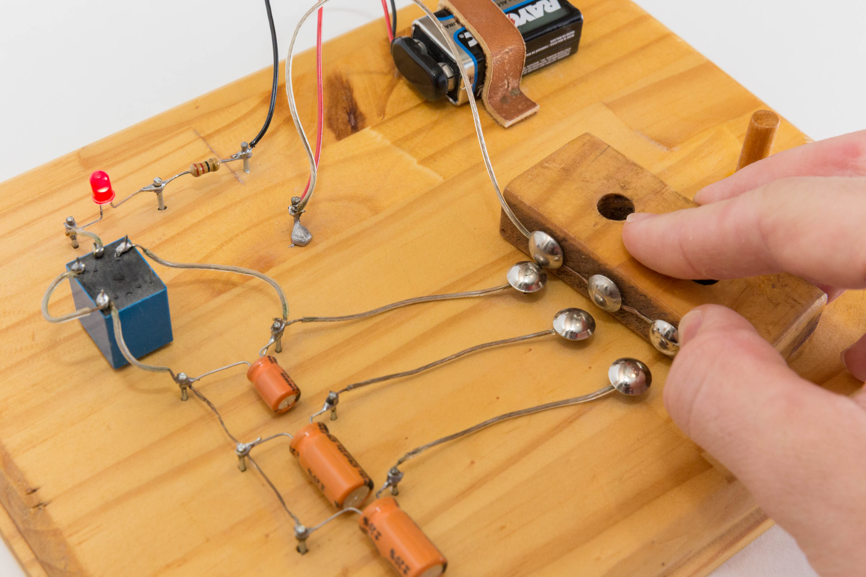
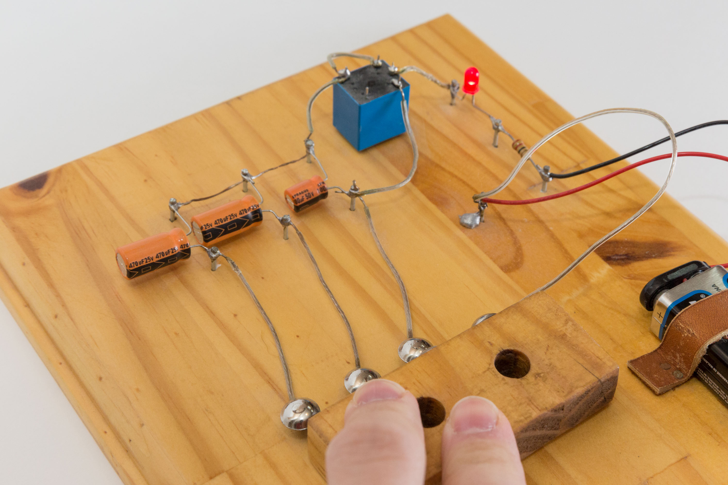
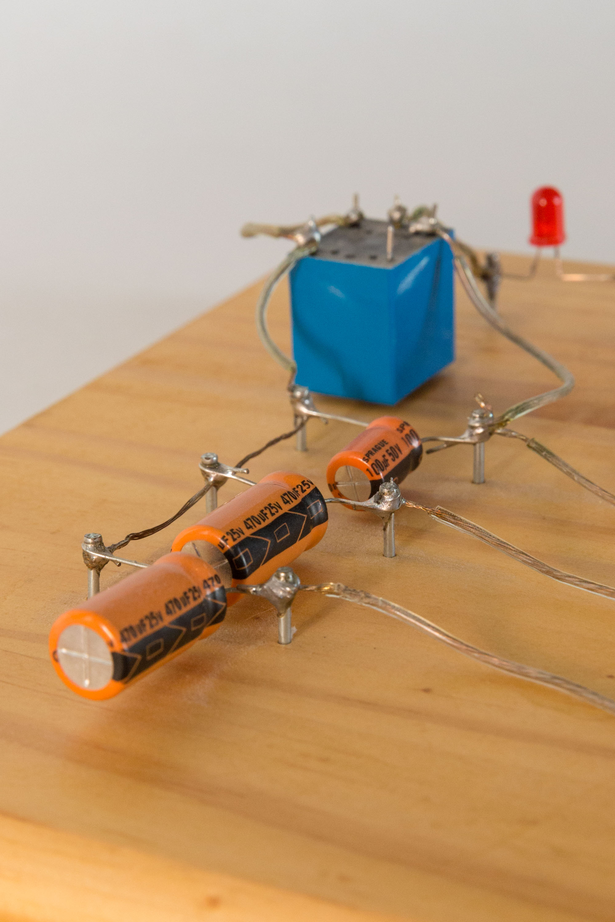
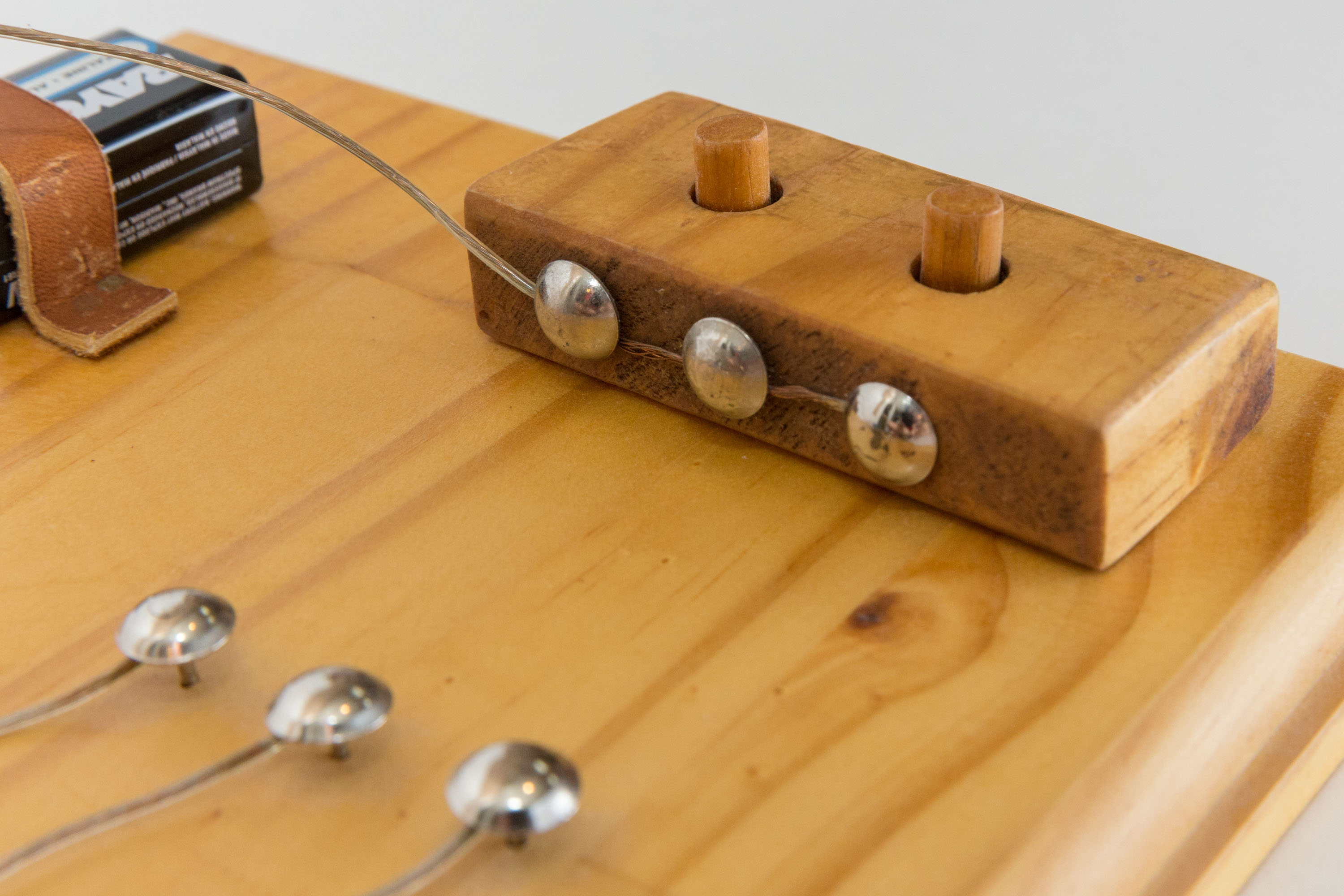
To change the speed of the oscillation you can change the size of the capacitor. I put 3 capacitors in a parallel circuit and made a special switch that I can use to control how many of the capacitors to use. For example, if I have 3 capacitors (10uF, 100uF, 100uF) in parallel, then you can create combinations like 10uF+100uF=110uF and 10uF+100uF+100uF=210uF. This is cool because the bigger the capacitor, the more time it takes to charge and discharge therefore the light flashes slower.
The way I made the board that I mounted my circuit on is with a table saw, a router, and a little bit of polyurethane. To cut the boards my dad and I used the table saw. We wore safety glasses to prevent wood pieces from getting into our eyes. I then made the edges with a router. Then I put polyurethane on it and let it dry. To get the nails in the right spot I put grid paper on my wood and made a design. I pounded the nails into the wood. To mount the wires and components onto the nails I used a soldering iron and solder to get them “glued” on to the nails. That’s how I made my project and how it works.
Pictures