4-H Electronics Project 2008
This post is one of a six part series documenting and archiving Nathan’s electronic projects created during his years participating in 4-H. To be clear, this project was done many years ago. During the winter months of 2017-2018, Nathan decided to archive his past projects as a way to remember and share them, hoping to inspire other beginning electronic hobbyists.
Summary
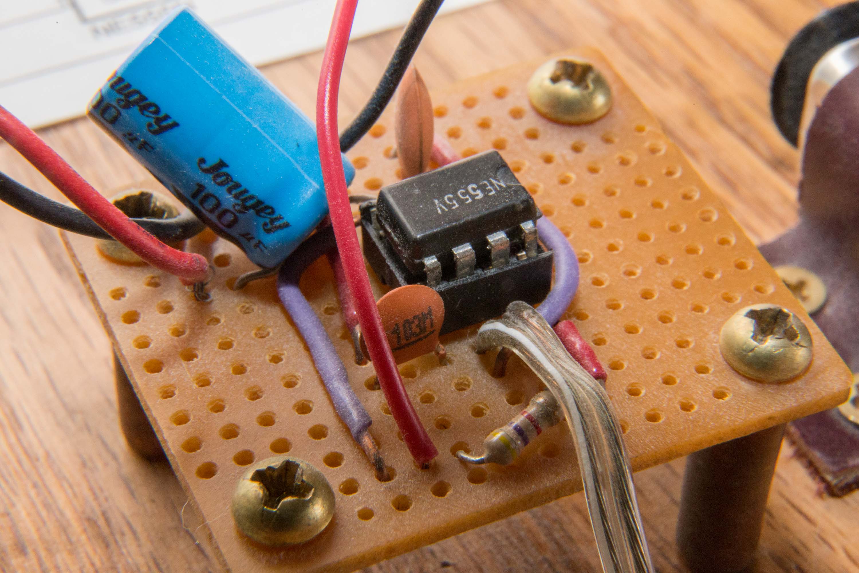
The 555 timer is a popular, cheap, and versatile integrated circuit (IC) that can be used in a multitude of different applications. This project uses the 555 timer to generate pulses that drive a speaker, creating tones. There are many tutorials online that explain the venerable 555 timer, so look around for a more detailed explanation of the 555 timer specifically.
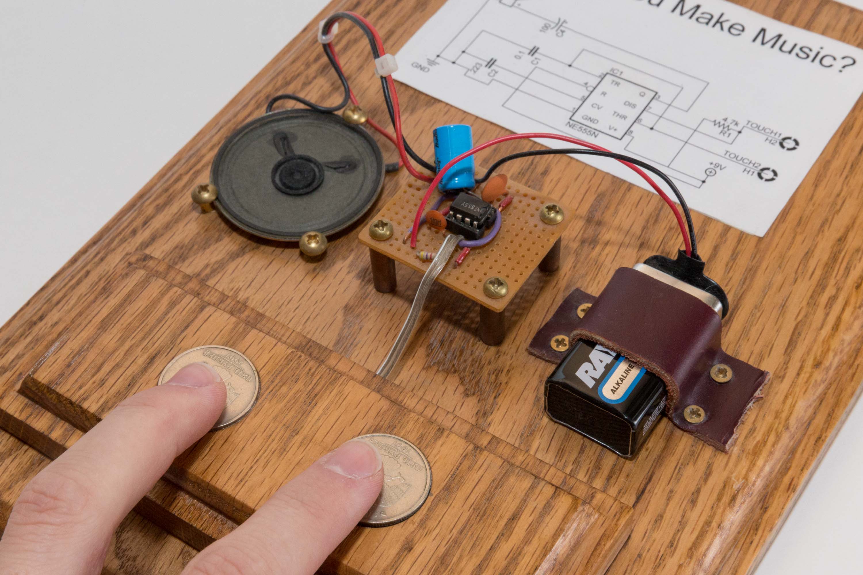
This circuit uses the 555 timer configured as an astable multivibrator: it produces a simple periodic square waveform. When skin comes in contact with both coins, an impedance is presented between pins 6 (Threshold) and 7 (Discharge) of the 555 timer. This impedance directly controls the frequency of oscillation of the output waveform which changes the speaker tone frequency. C4 provides ac coupling between the output of the 555 timer and the speaker.
Configured as an astable multivibrator, it can be shown that the oscillation frequency of the 555 timer follows this equation:
$$ f = \frac{1}{\ln{2} \cdot (R_1 + 2R_{SKIN}) \cdot C_1 } $$
Letting $R_1 = 4.7k\Omega$, $C_1 = 10nF$, $R_\text{SKIN} = 1k\Omega..100k\Omega$, the circuit generates tones within the audible range of humans (~700Hz to ~21.5kHz).

This plot paints a clear picture of circuit operation: when there is large resistance between the coins (lightly pressed fingers), the tone is very low; small resistances (firm/wet fingers) produce very high tones.
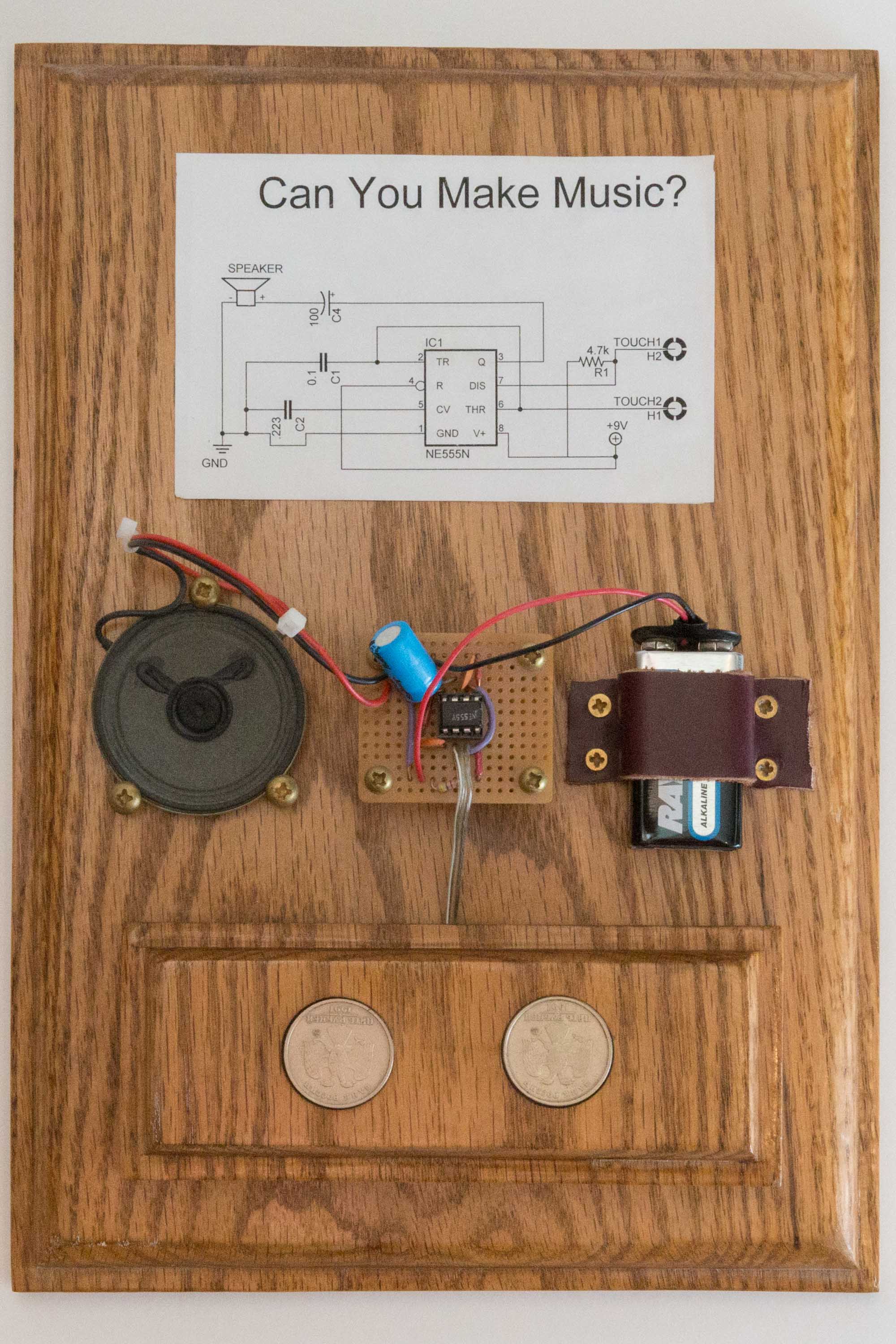
Schematic
View the PDF version: click here.

Original 4-H Report
The text written below is directly from Nathan’s report given with this project at the 4-H Exposition of 2008, when Nathan was eleven years old.


I like things that make noise, so this year I learned about using people as resistors, and 555 timers. I learned that people are conductors so an electric charge can pass though them, but they can’t feel it. I also learned about 555 timers. We searched on the internet to find a circuit so I could use what I learned to make a fun 4-H project. The circuit was for a little organ, but as we were constructing the proto type, we found that it was more fun to use your body as a resister.
We went to Radio Shack and bought a 555 timer. My dad told me a 555 timer is a general integrated circuit. It is a good base for a circuit that needs to be accurate with time and pulses. We already had the other components, so we didn’t have to buy anything else.
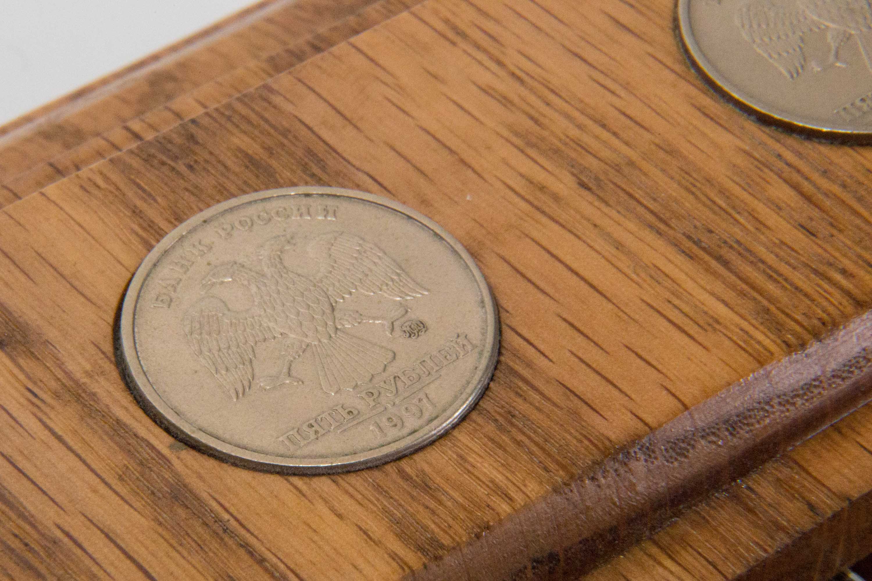
The circuit works on the basis of the resistance of our body. When you put your fingers on the coins, you are inputting yourself as a resister in the circuit. The more resistance you have, the lower the sound is. If you lick your fingers, then the sound goes higher because the resistance is lowered.
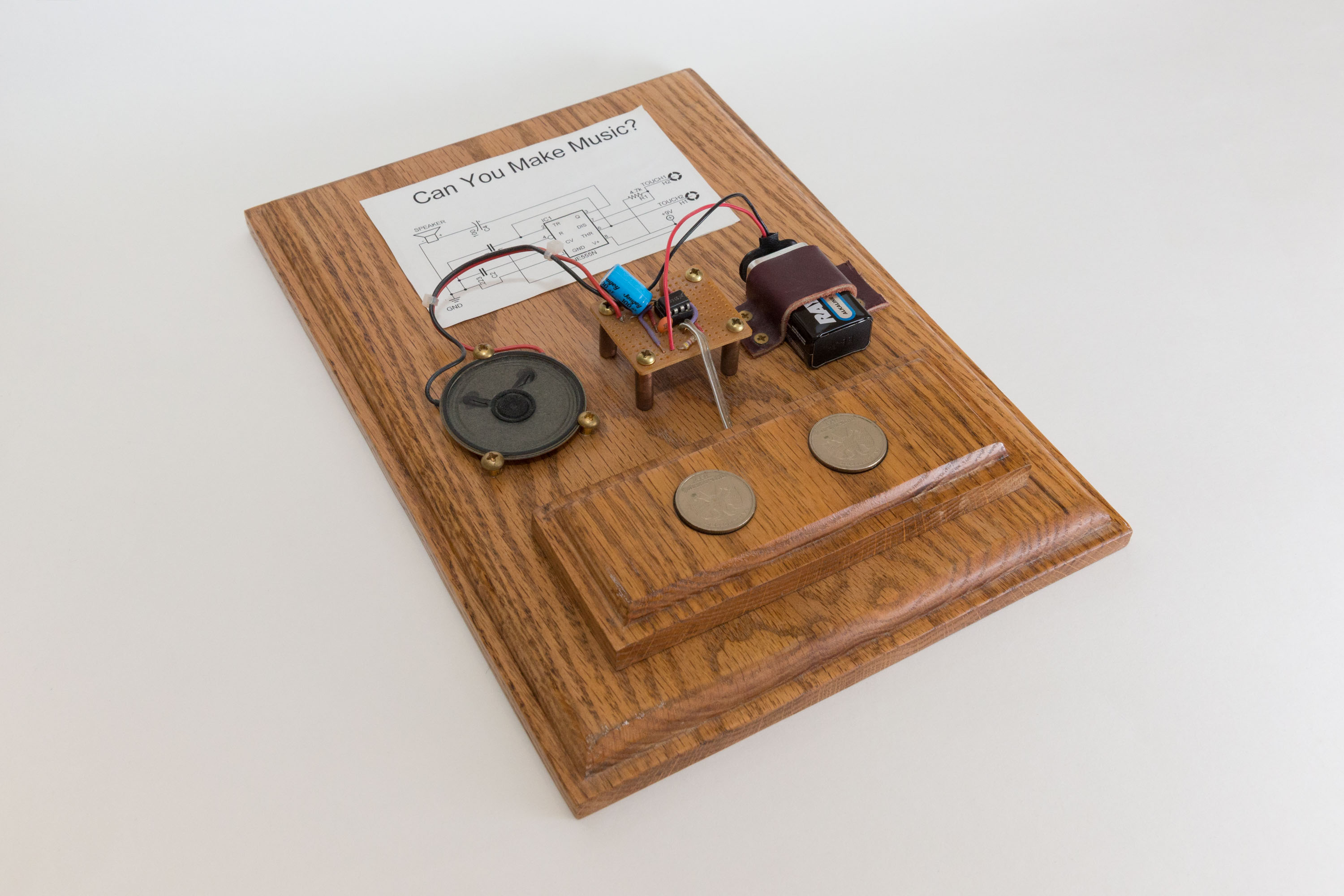
The way I made the board that I mounted my circuit on is with a table saw, a router, and a little bit of polyurethane and stain. To cut the boards my dad and I used the table saw. We wore safety glasses to prevent wood pieces from getting into our eyes. I then made the edges with a router. Then I put the stain and polyurethane on and let it dry. To get all of the components in the right spot I measured and got everything even. I did the soldering with the guidance of my dad. That’s how my project was made and how it works.
Pictures