4-H Electronics Project 2009
This post is one of a six part series documenting and archiving Nathan’s electronic projects created during his years participating in 4-H. To be clear, this project was done many years ago. During the winter months of 2017-2018, Nathan decided to archive his past projects as a way to remember and share them, hoping to inspire other beginning electronic hobbyists.
Summary
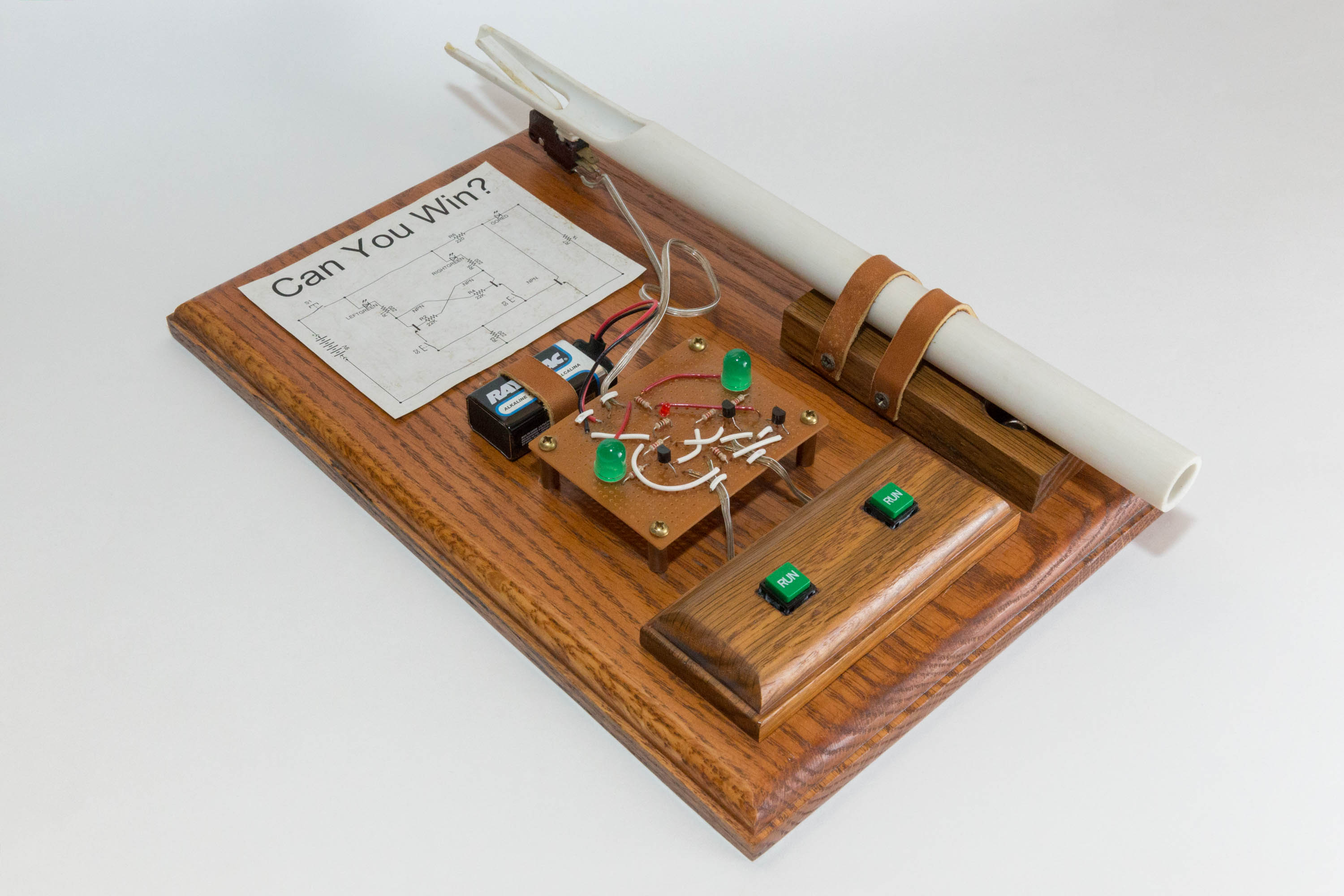
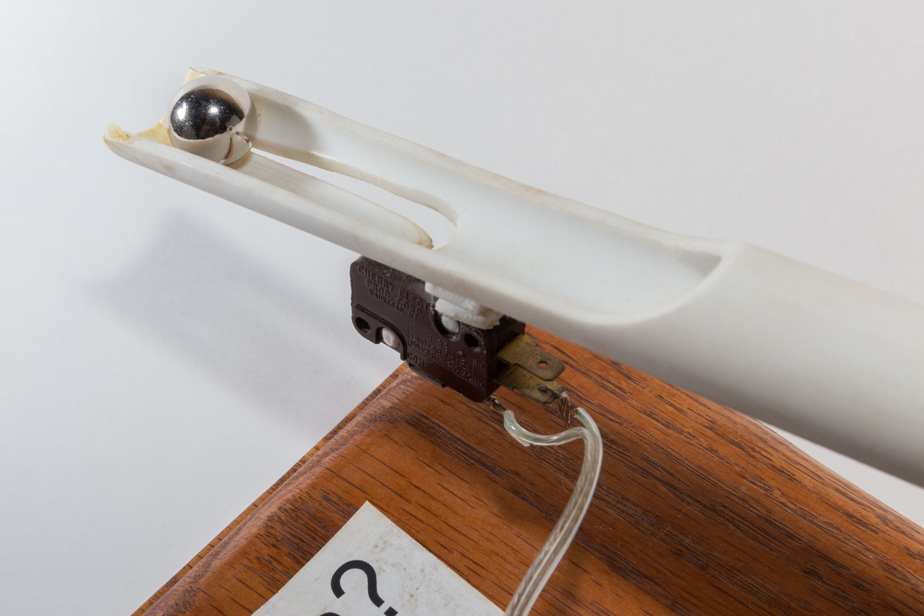
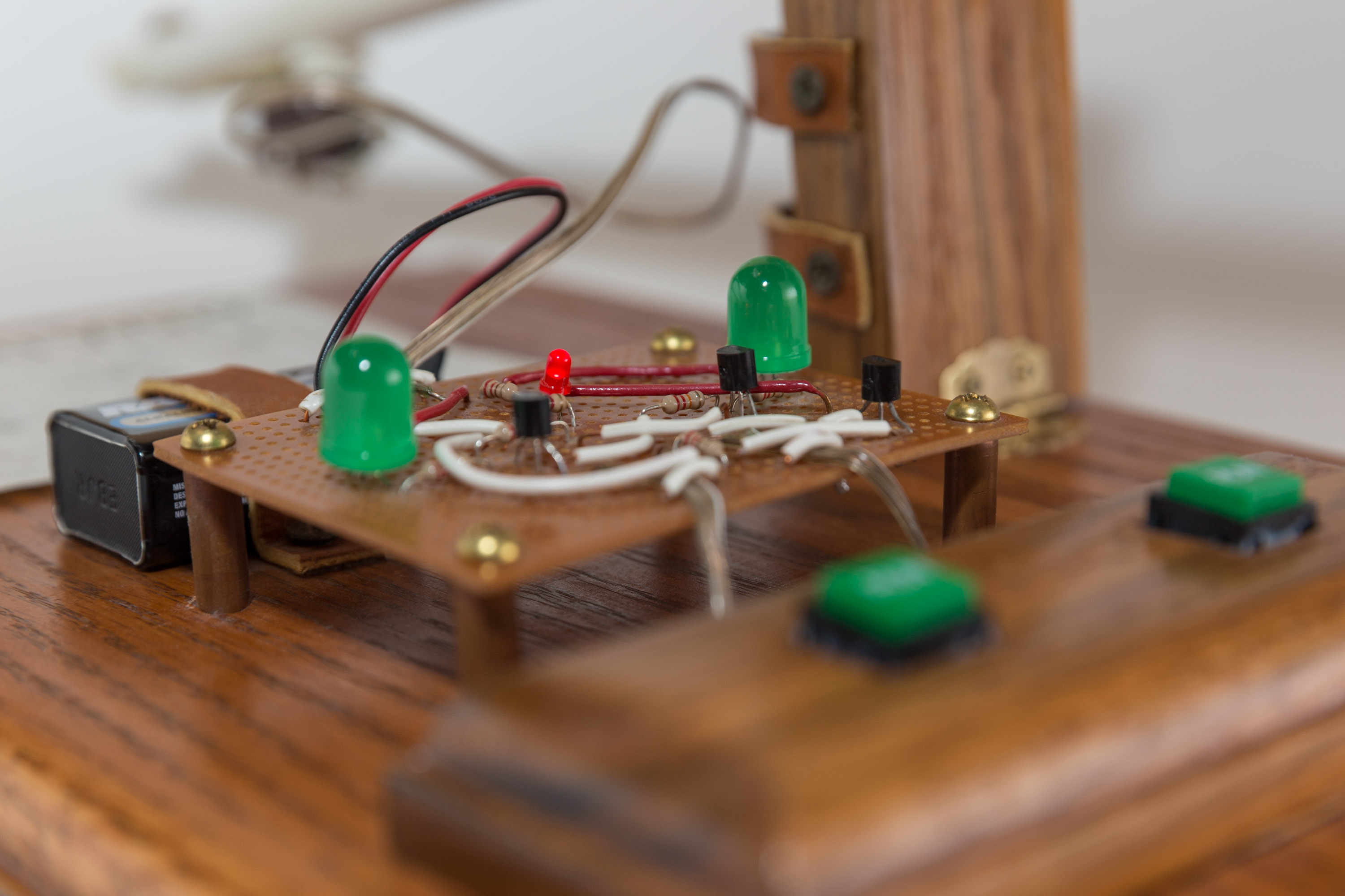
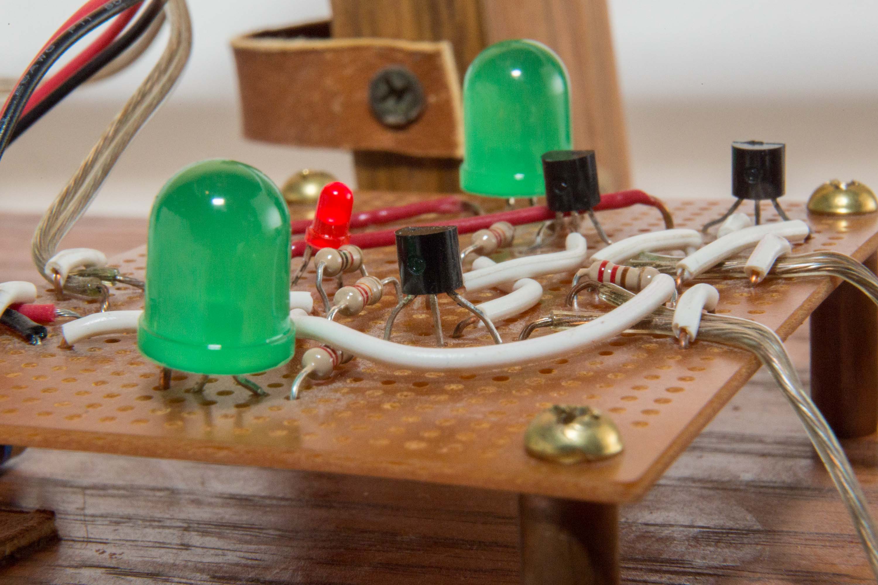
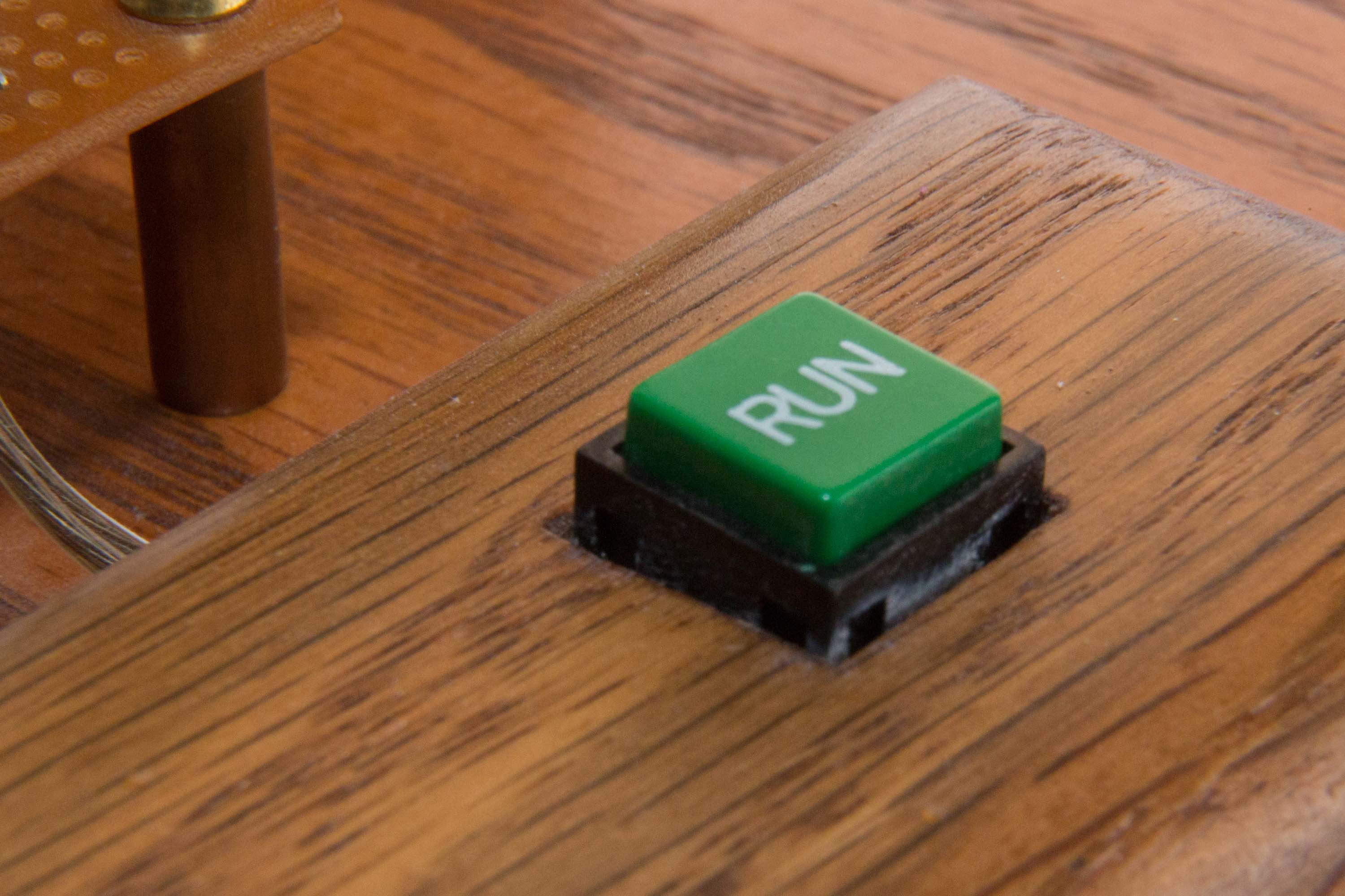
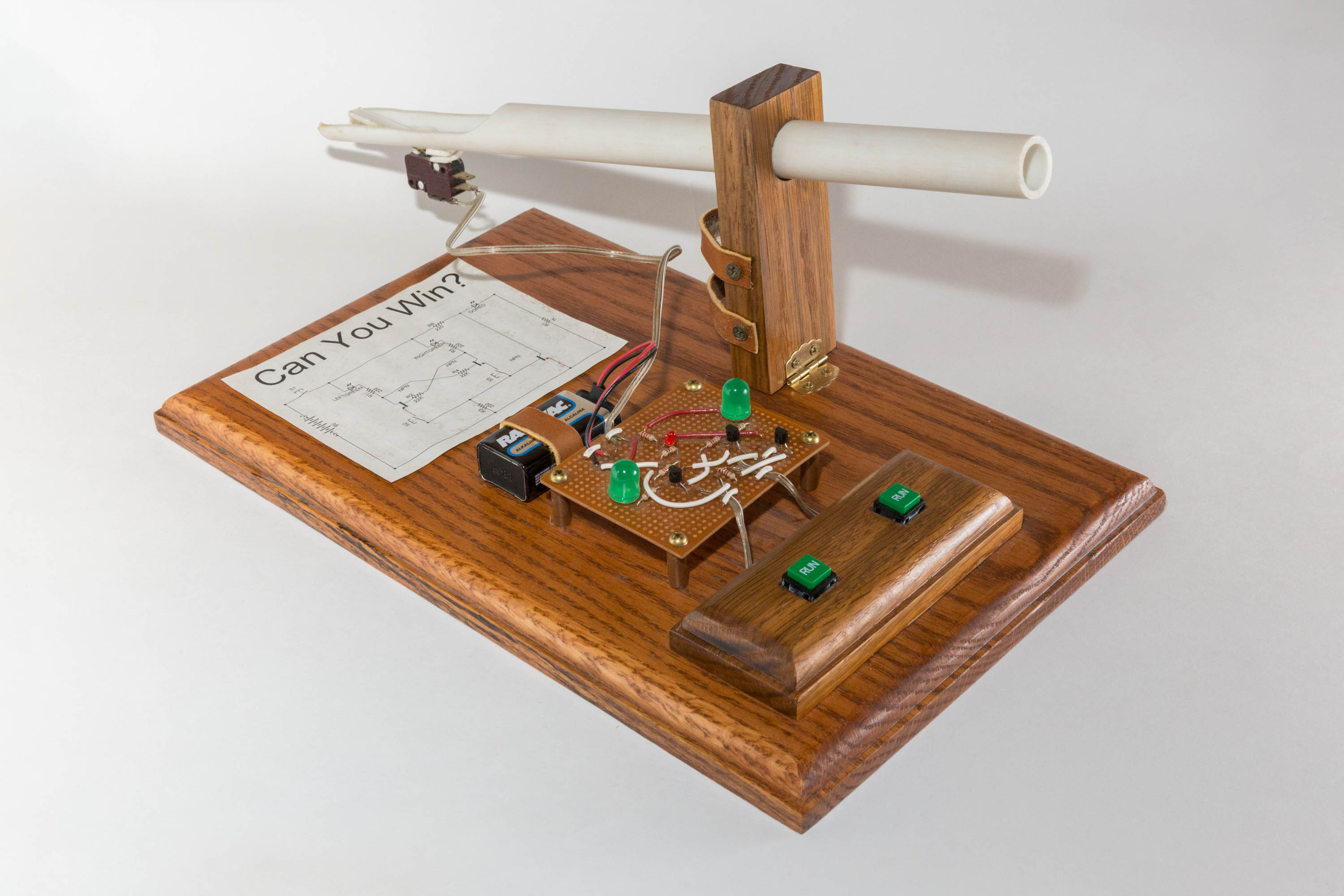
Using rolling balls and transistors to test human reaction time might seem strange, but that is exactly what this project does. This “game” was designed to determine who of its two players has a faster reaction time. To start, one player inserts a metal ball into the PVC tube. After rolling down the pipe, the ball activates the limit switch which causes the red LED to illuminate. At this point, both players press their respective “RUN” button as fast as possible. The big green LED of the faster player will illuminate, indicating a win!
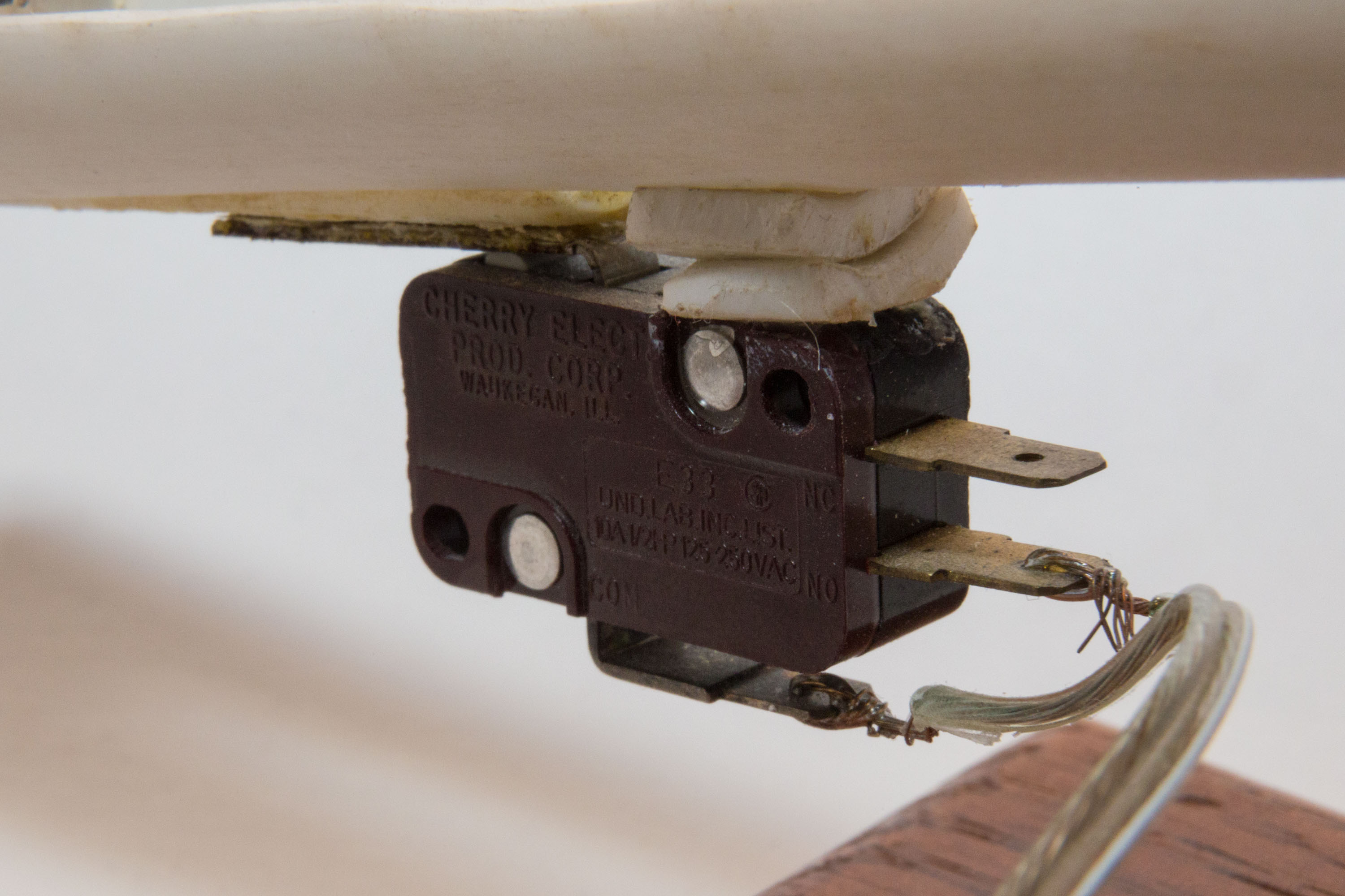
This fairly simple circuit uses three transistors to control three LEDs. At start, S1 (the limit switch on the PVC pipe) is open which keeps the circuit disabled. Once activated, LED3 (red “go” LED) illuminates. Since both player switches are open, no current flows through the middle of the schematic, so only the outer ring is active.
When the first player presses their button, a current path is enabled through their LED. This current illuminates their LED as well as activates U3 which bypasses the red “go” LED, turning it off. If the other player then presses their button, their LED stays off because there is no voltage potential at their transistor’s base.
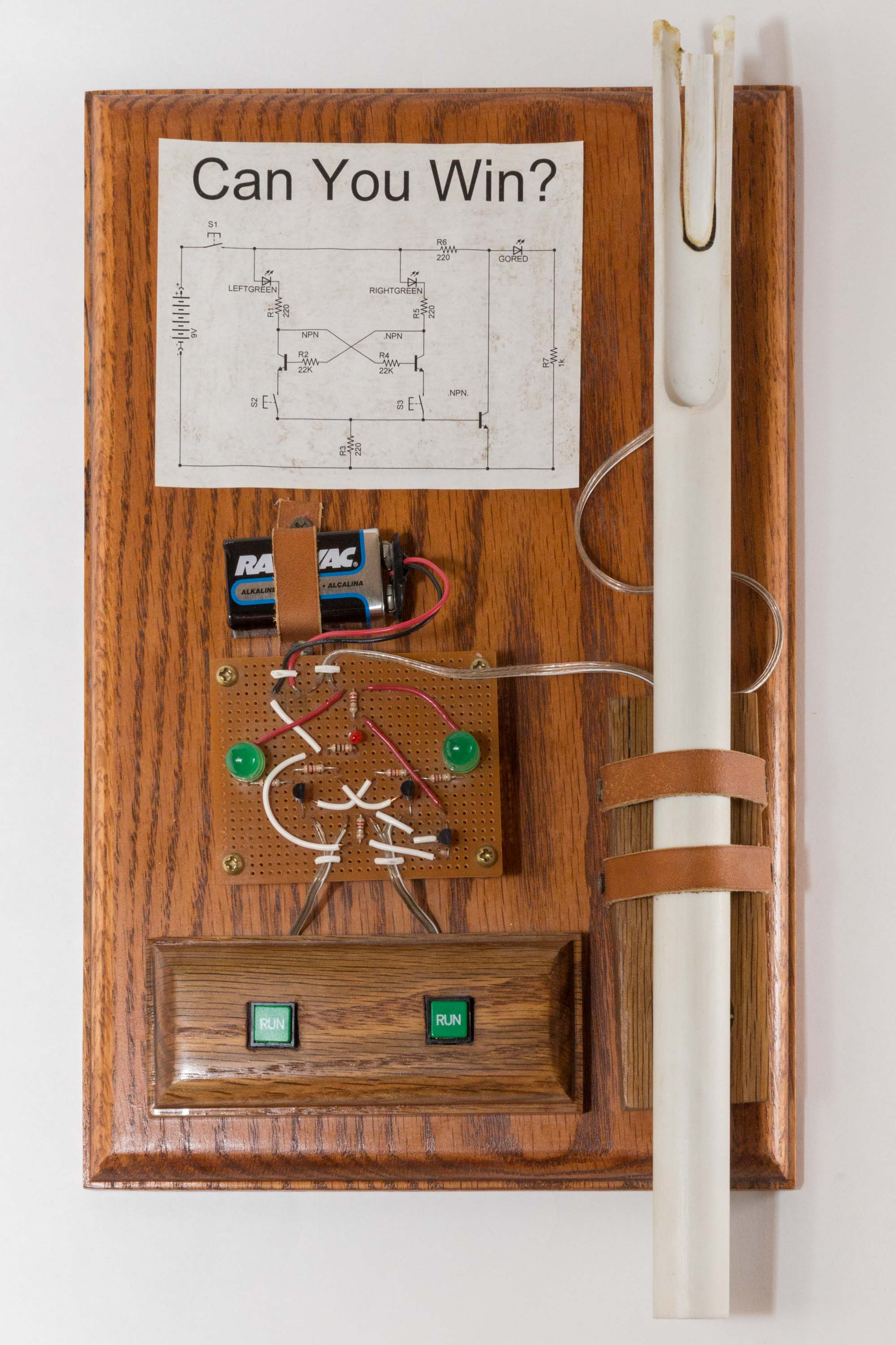
Schematic
View the PDF version: click here.

Original 4-H Report
The text written below is directly from Nathan’s report given with this project at the 4-H Exposition of 2009, when Nathan was twelve years old.
This is my 4th year in Electricity and my 1st year in Electricity 4 or Electronics. My year starts when I look for cool circuits to build. I look through old magazines like 101 Electronic Projects to find ideas on what to build. After a long time my dad and I found a circuit that is a game. There is a switch that turns on a light and then you have to press a button before your opponent in order to win. After you press the button, it doesn’t let the other person’s light go on, and it turns off the “go” light. This is the first time I’ve built a circuit with transistors. Two years ago I built a circuit that used a relay and I learned that a transistor is almost like a relay. A transistor acts like a switch that turns on and off based on the amount of current applied to the base of the transistor. A transistor has a collector, a base in the middle, and a emitter on the opposite side of the collector. The other main components are resistors. A resistor is a component that reduces the voltage or resists some of the current. I also used three LEDs. A LED is a Light Emitting Diode that acts like a diode by only letting current through when the leads are connected to the right polarity. If it is connected right then the LED lights up.
The whole circuit works using the principle of fractional current. For example, the red LED (the “go” LED) is in series with a 1K and 220 ohm resistor. The LED and the 1K resistor are in parallel with a transistor. When the transistor is off, then the resistance is in the millions; but when it is on, it is close to 0 ohms. With fractional current when the transistor is off, almost all the current flows through the LED. When the transistor is on then current bypasses the 1K resistor and the LED and flows through the transistor instead. That cuts off the red LED. If this was a computer statement then it would 0.79”behave like a NOT expression. When the transistor is on, the LED is off, but when the transistor is off the LED is on.
The game is played with two transistors, two LEDs, two switches and five resistors. The circuit wiring looks confusing so I’ll explain it to you. Initially the current attempts to flow equally through both LEDs, the matching transistor and to the opposite transistors base. However, it cannot complete the circuit out of the collector because the switch is open. When the player presses the switch this completes the circuit to light the LED and in the process diverts the current away from the opposite transistors base and prevents the opponents LED from lighting when the opponents switch is pressed. The circuit is symmetrical because the first player to press a button prevents the opposite LED from lighting.
This was a very challenging project to construct because there were 35 different pieces that needed to be assembled correctly in order for it to work. First I assembled the circuit on a solderless breadboard to see how the circuit worked. It seemed to work well so the next step was to put it on a circuit board. I learned to form the components in the right length to fit the board hole. Then I soldered each component to the circuit board and created solder bridges to form wires to connect the components that were supposed to be connected with my dad watching. When I was done I tested it and it did not work properly. I asked my dad for help and we used a digital multimeter to check for bad solder joints and to compare resistances with the prototype on the solderless breadboard. I fixed two bad 0.79”solder joints and moved a resistor I had soldered in the wrong place on the circuit board. When I tested it again it worked only a little better. I double checked everything and I couldn’t see anything that was wrong. With the help of my dad we found that bypassing the resistor connected to the “go” transistor caused the circuit to work correctly. We fixed the circuit by removing the resistor and replacing with a wire jumper. Finally I was SO HAPPY that the circuit worked like I had originally designed it to work!!!!!
I cut the display board and routed to the edge of the boards to make them pretty. After that I stained the board and put on a polyurethane finish. I used the drill press (my FAVORITE tool) to drill a couple holes. Then it was ready to put together. I used a computer ECAD program to draw a circuit diagram for my display board. This was my most challenging project yet and I’m happy that I learned how to use transistors to construct a fun game.
Pictures