4-H Electronics Project 2010
This post is one of a six part series documenting and archiving Nathan’s electronic projects created during his years participating in 4-H. To be clear, this project was done many years ago. During the winter months of 2017-2018, Nathan decided to archive his past projects as a way to remember and share them, hoping to inspire other beginning electronic hobbyists.
Summary
During early 2010, I became very interested in photographing high speed events, like balloons popping, glass shattering, etc. These events happen very fast, so human reflex time and camera shutter lag become major problems. To help solve these issues, I built this circuit.
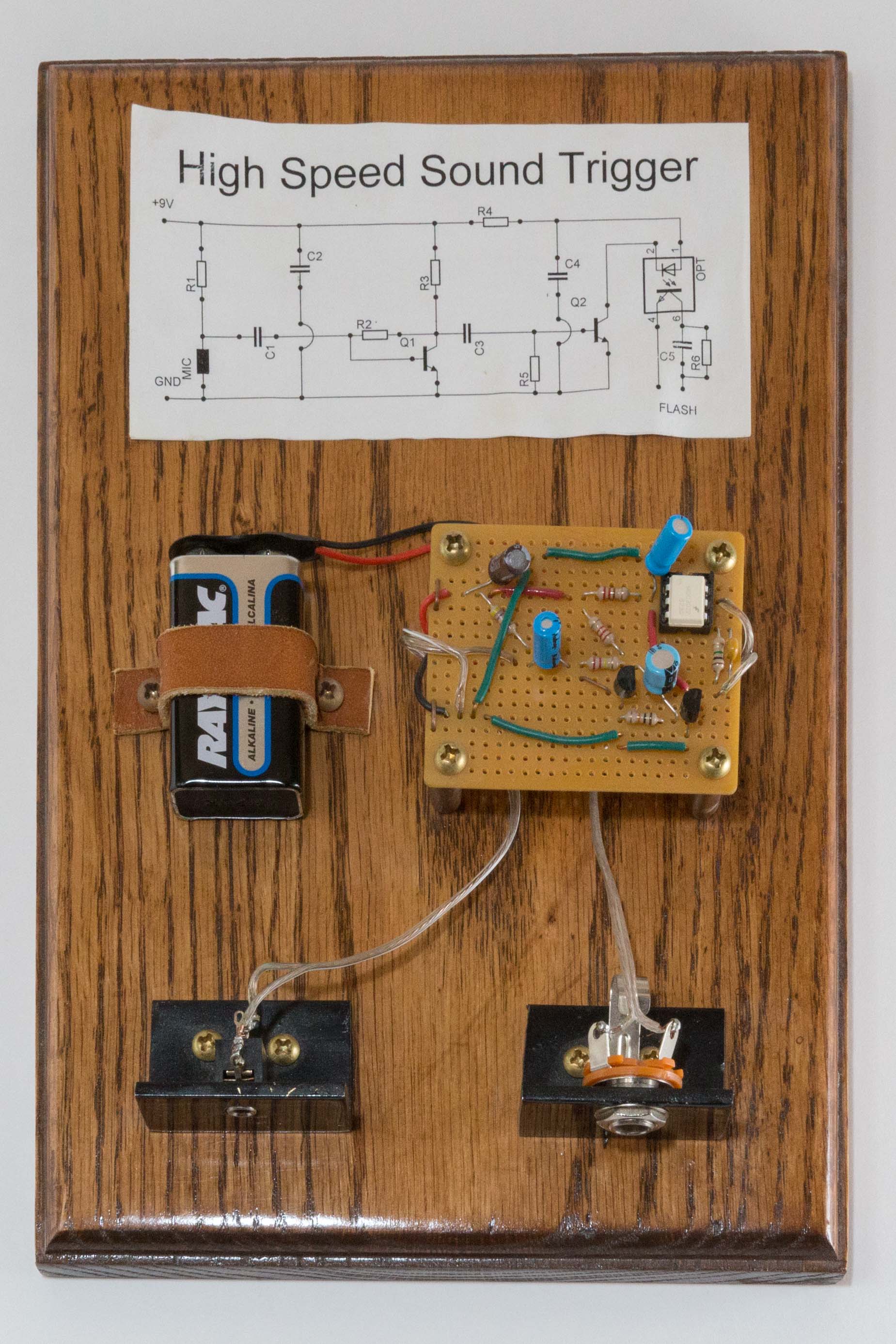
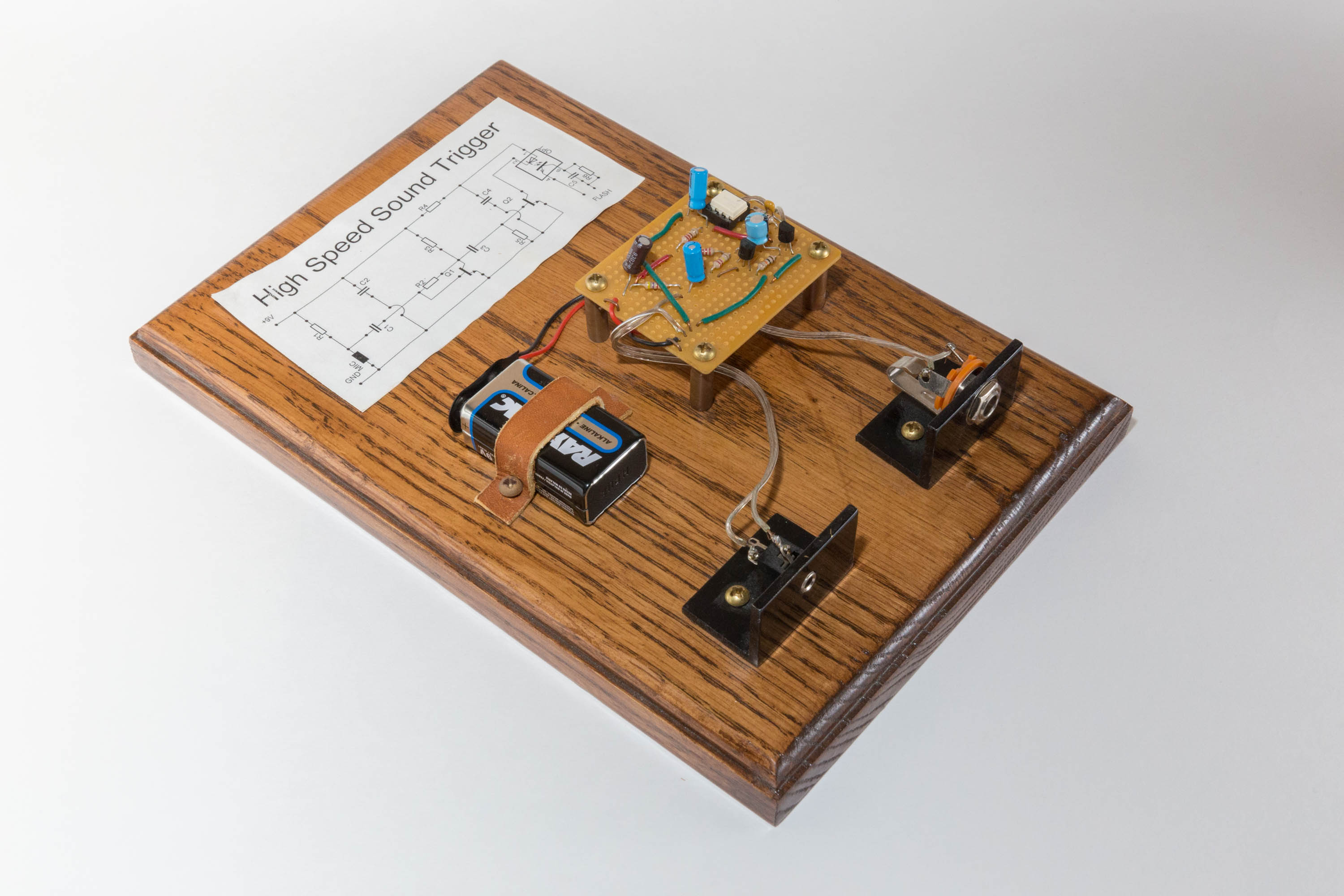
This high speed sound trigger circuit activates an external camera flash based upon input from a microphone. When a loud enough sound is detected, the two flash output signals are shorted together, triggering the flash. To take a picture of a balloon popping, one must simply turn off all room lights, start a long exposure on camera, and pop the balloon. Since the room is dark, the only light to which the camera is exposed is from the flash, which in turn freezes the balloon mid pop. By photographing in a dark room, the “shutter speed” is effectively the flash duration. Setting the flash to lower power decreases flash duration (read this article for analysis of flash duration vs power).
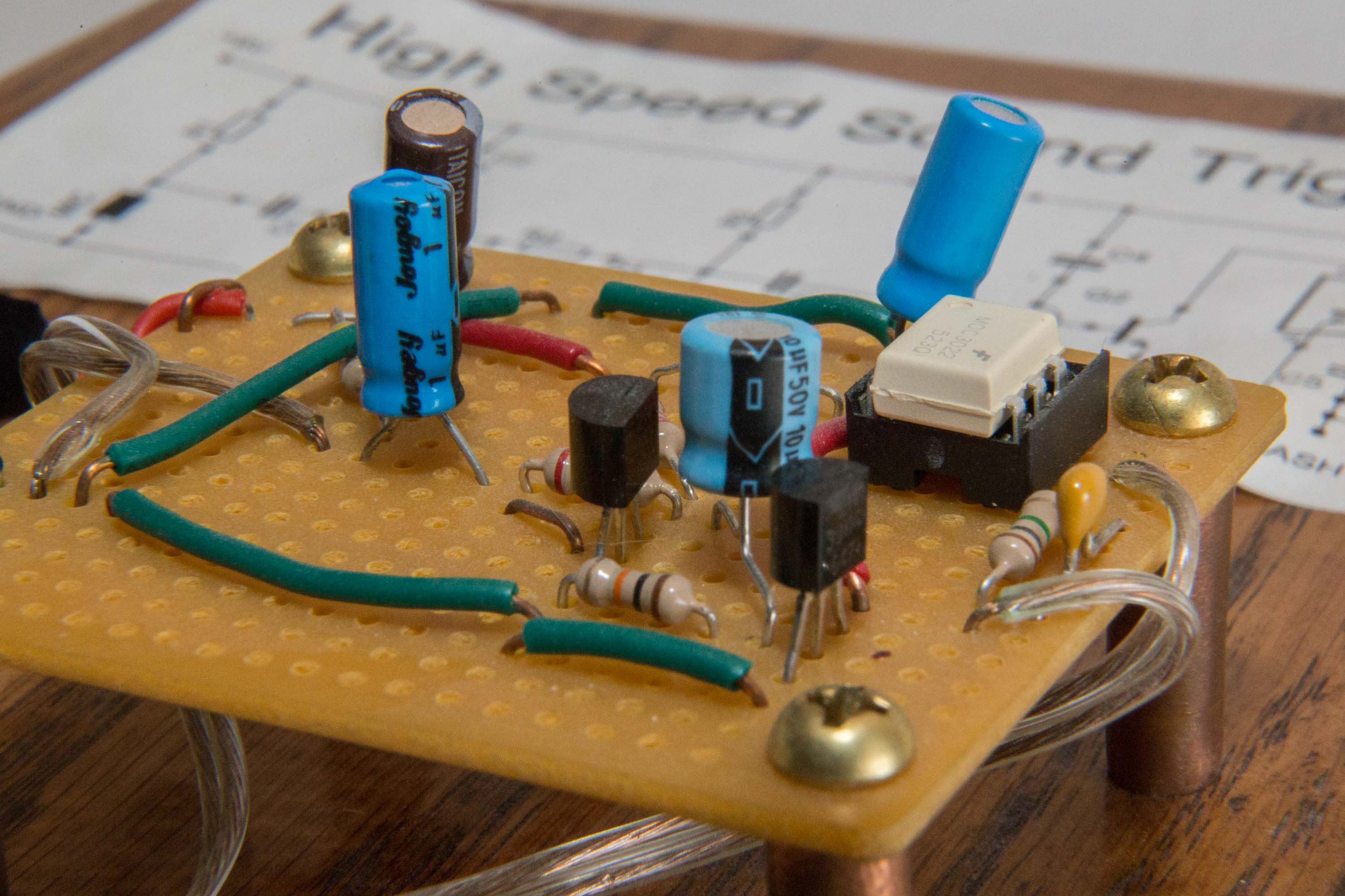
To detect loud noises with minimal latency, a simple two transistor amplifier is used. R1 and C1 in combo with the electret mic create an ac coupled signal that is amplified in stage 1 via transistor U1. This amplified signal is then amplified again in stage 2 via transistor U2. The output of stage 2 is used to trigger an optical isolator, which in turn triggers the flash. This provides isolation between the flash and the amp circuit (some flashes send 300V+ through their contact points at activation).
Schematic
View the PDF version: click here.

Original 4-H Report
The text written below is directly from Nathan’s report given with this project at the 4-H Exposition of 2010, when Nathan was thirteen years old.

This year for electricity I decided to do a high speed, sound flash trigger. This is a device that you plug in a microphone and a flash and it fires the flash when sound is heard. You might ask how this is useful. It’s useful for taking high speed pictures of balloons popping, or other loud objects that do something. Another question you might have is how this would help you take a picture. To use this circuit, you’d need a dark and silent room. After you make sure that there would be no random sudden loud noises, you’d set a camera on a 2 second exposure, and focused on the subject. To take the picture, you need to start the exposure, and while it’s going, do the action to trigger the flash. Because the room is dark, the 2 second exposure will not overexpose. The light in the picture and the “speed of the exposure” is then controlled by the duration of the flash.
The Creation of This Project
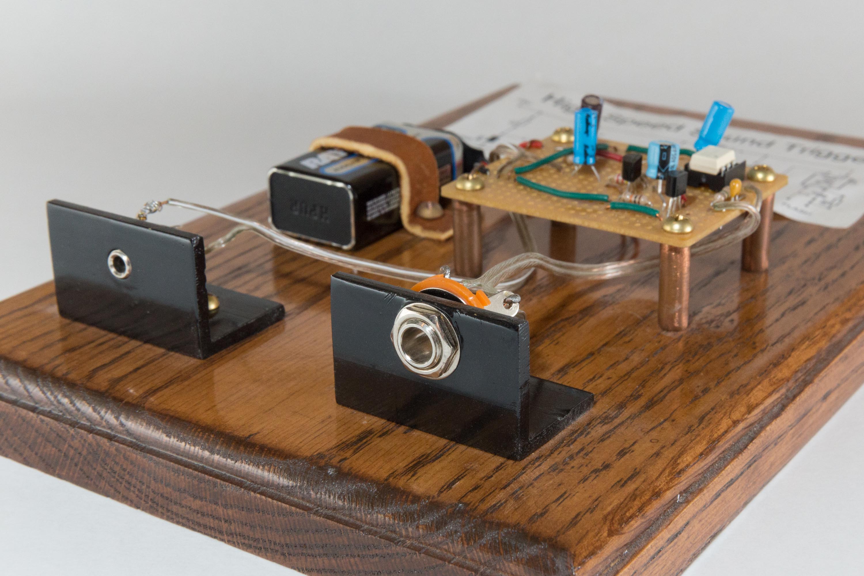
As always with my electricity projects, they start off with the display board. Since my dad has the saw and router, it’s as easy as stepping into the garage to get the display board cut and routed. I do the cutting, with the help of my dad. (I don’t want to chop off a finger or something.) I then proceeded to route the board with my dad standing near by to help if anything went wrong. After all the cutting was done I had to sand it smooth. Finally, the board was ready for staining and putting on polyurethane.
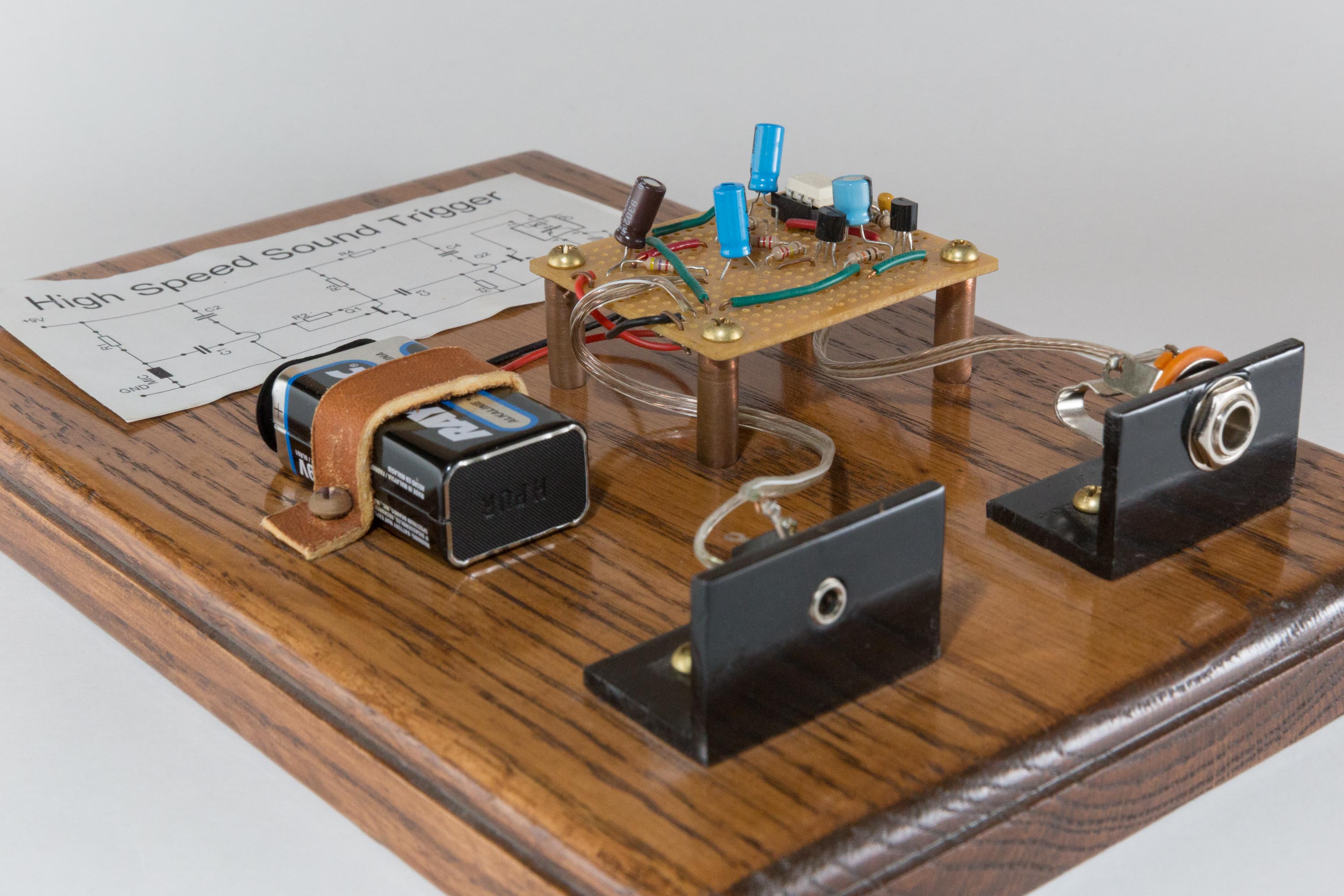
While the board was drying, I had a good amount of time to actually work on the electricity part of the project. The first step was to prototype the circuit that I found on the internet with a solderless breadboard. It seemed to work fairly well but not completely. I’m not very good at changing circuits to make them work, so my dad helped me with it. The only problem was that one resister was way too big. Other than that the circuit was perfect. After I got the solderless breadboard version of the circuit working, it was time for putting it on a perf-board. First though, I needed a layout. In years past at this step, I started drawing a layout but it always “flopped” and didn’t work so my dad helped out. But this year, I did it all by myself. The only thing my dad did was to proof it to make sure it would work and that everything I was trying to do was possible (putting 3 leads in 1 hole is not possible). I then had the task of bending all the components to the right shape and size. When this was done and they were all in the board, I soldered them all in. In years past at this step, too, my dad normally helps. He never solders himself, but he watches closely and guides me. But this year, he wasn’t even in the room! I got to solder by myself with no one helping me. This really improved my skills and such. When all the pieces were in, I made all the solder bridges to complete the board. Now it was time for testing. I knew that it wouldn’t work the fist time so that’s what I was preparing myself for. But, to my surprise, everything worked perfectly the very first time! Maybe there is a pattern here. My designs, my solder, everything works. Just a thought. :-)
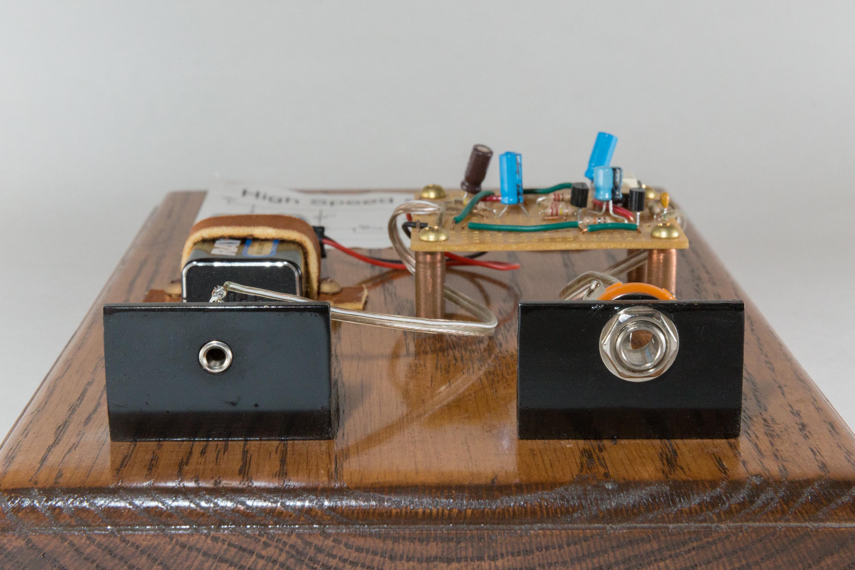
Anyway, I had to strap down after this part. I was running out of time. I only needed to mount the components to the board and draw up the circuit for the board top, but it seemed like a lot to do. I started all of this by getting some “L” braces and cutting them to fit the microphone and flash inputs. Next, I put in connectors and soldered them in. I had to make sure that the microphone polarity was correct because if it wasn’t, the circuit wouldn’t work. But finally, all that was left was to make the circuit schematic and drill the holes to mount everything into the board. The schematic wasn’t hard after I figured out the program, and the drilling just needed to be lined up right. Finally, I was done.
What I Learned
This year in electricity, I learned a lot of things. One of them was how to amplify sounds with transistors and how to use a opt-isolator. The left transistor in this circuit takes the voltage from the microphone and makes it stronger so that it can be used. When the sound coming off of the microphone is loud enough, it triggers the base of the second transistor which sets off the LED inside of the opt-isolator. Then the triac turns on to trigger the flash. The reason why I use a opt-isolator is because it isolates the flash from the rest of the circuit. Normally, circuits run good at about 5-9 volts, but some flashes need about 300 volts to flow through the connector wire for it to trigger. If all 300 volts went through the circuit, it would get fried. Thanks to the opt-isolator, the flash and the rest of the circuit do not have an electrical connection. They are just connected through light.
Pictures