4-H Electronics Project 2011
This post is one of a six part series documenting and archiving Nathan’s electronic projects created during his years participating in 4-H. To be clear, this project was done many years ago. During the winter months of 2017-2018, Nathan decided to archive his past projects as a way to remember and share them, hoping to inspire other beginning electronic hobbyists.
Summary
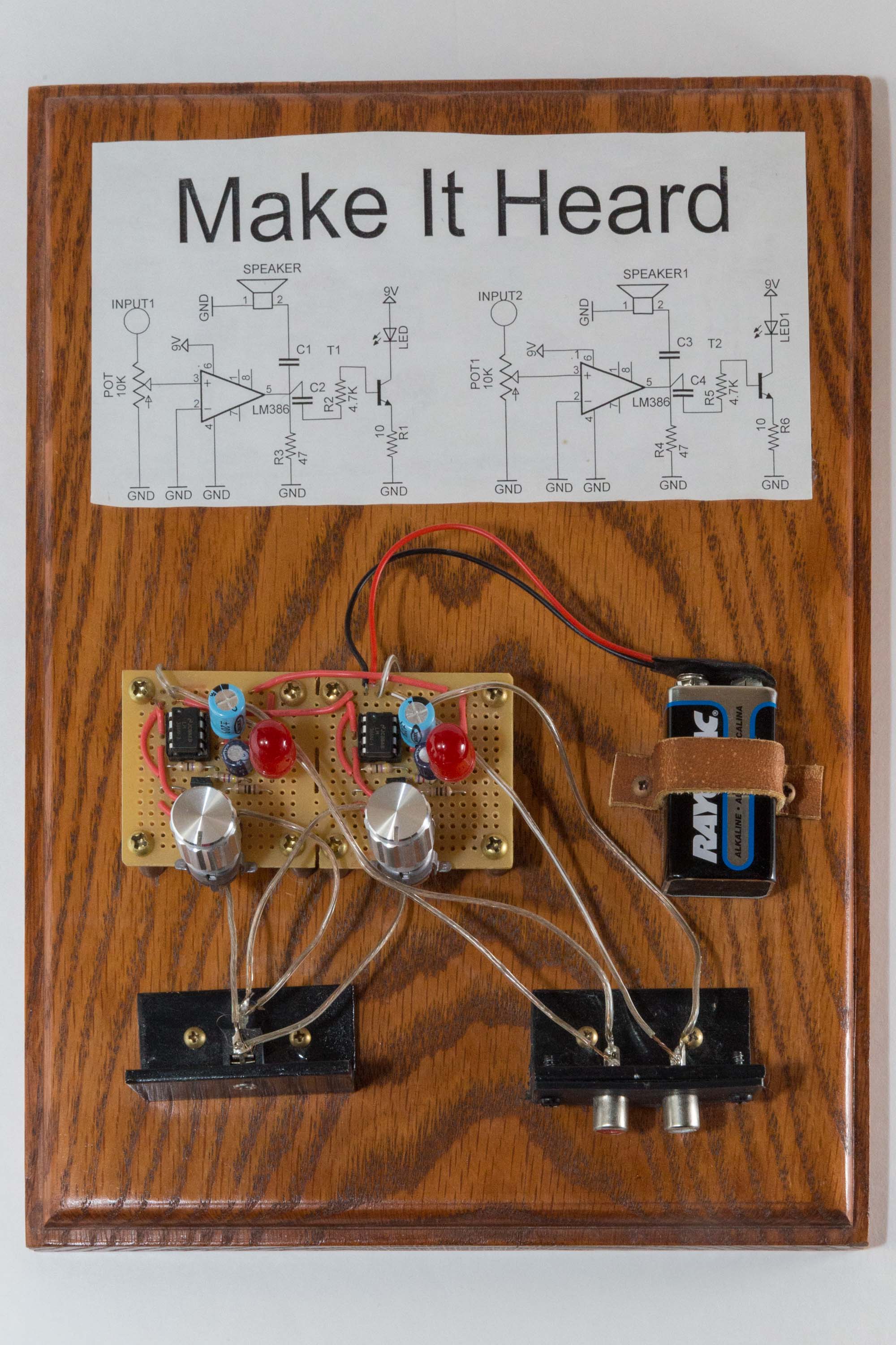
This basic audio amplifier circuit is a perfect introduction to integrated circuits (ICs) on a tight budget, plus it produces a useful result. The LM386 IC is used as the backbone of this amplifier, reducing component count and complexity. Take a look at the LM386 datasheet to learn more about it. To amplify stereo audio sources, simply duplicate the whole circuit, as seen in the schematic below.
Each channel of the input audio source is connected to the +/- inputs of a LM386 IC. Volume is controlled via a potentiometer on the positive input line. Looking at Channel 1 in the schematic below, C1 in series with the speaker output forms a passive high pass filter; this prevents dc signals from being directly applied to the attached speaker. C2 provides ac coupling of the LM386 output to the transistor controlling LED brightness, effectively emulating the audio signal into the speaker. Because of C1 and C2, a dc input signal will not create steady-state output at the LED or speaker.
Schematic
View the PDF version: click here.

Original 4-H Report
The text written below is directly from Nathan’s report given with this project at the 4-H Exposition of 2011, when Nathan was fourteen years old.

This year I decided to make an iPod Amplifier. I’ve started getting more and more interested in audio equipment, and since I am only 14, I have a very small budget… So, I try to make the things I want to use.
A while ago, I bought some cheap computer speakers on sale and some really cheap speakers from Goodwill. Together they cost only about 15 bucks. Not much for some good stuff. I figured I could take apart the computer speakers to get the raw speakers and the audio amplifier. When I did, I found that the speakers in the unit were pretty bad. So, I wired up the Goodwill speakers to the harvested amplifier circuit and got amazing sound for only 15 dollars. I liked it a lot, but it didn’t always work because I used alligator clips to make the connections. ;) …and it ran off of an AC wall-wart which converted 120V AC to 12V AC… This meant no battery. That’s why I wanted to build my own - a battery powered iPod Amp that was reliable.
The Creation
As always with my electricity projects, they start off with the display board. Since my dad has the saw and router, it’s as easy as stepping into the garage to get the display board cut and routed. I do the cutting now that I actually know what I’m doing. My dad just stands and watches (to make sure I don’t want to chop off a finger or something). I then routed the board to give it a nice edge. After all the cutting was done I had to sand it smooth. Finally, the board was ready for staining and putting on polyurethane. While the board was drying, I had a good amount of time to actually work on the electricity part of the project. This year, my dad did almost nothing to help me at all. He found a chip for me to use, the LM386, and then said, “Get started.” So I did.
I looked on the internet for a good simple circuit to use and finally found one. The first step was to prototype the circuit that I found with a solderless breadboard. It seemed to work fairly well but not completely. It clipped the audio and sounded fuzzy. I started to tweak the sizes of the components and take them out to see what every component added to the circuit. I finally ended up with a really good sounding amp. The only problem was that I took out all the parts to get it to sound the best it could. I thought it would be a bad 4-H project; just having a chip wired into a board with no actual components. Then my dad suggested that I add on a light organ. I didn’t know what that was, so I googled it and found out that it was circuitry that flashed lights to the music. I liked it but I couldn’t find a simple circuit that explained how it worked. So, my dad helped me find a circuit. It was actually for a bar graph that light up with the loudness of the song. I didn’t want something that fancy, so I modified the circuit to only blink one LED. I tested it on the solderless breadboard, along with the other part of the amplifying circuitry and tweaked some more values. Finally I got something I liked!
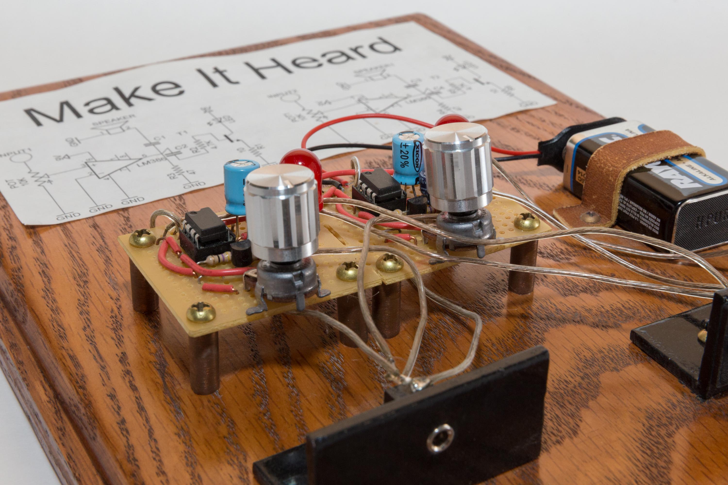
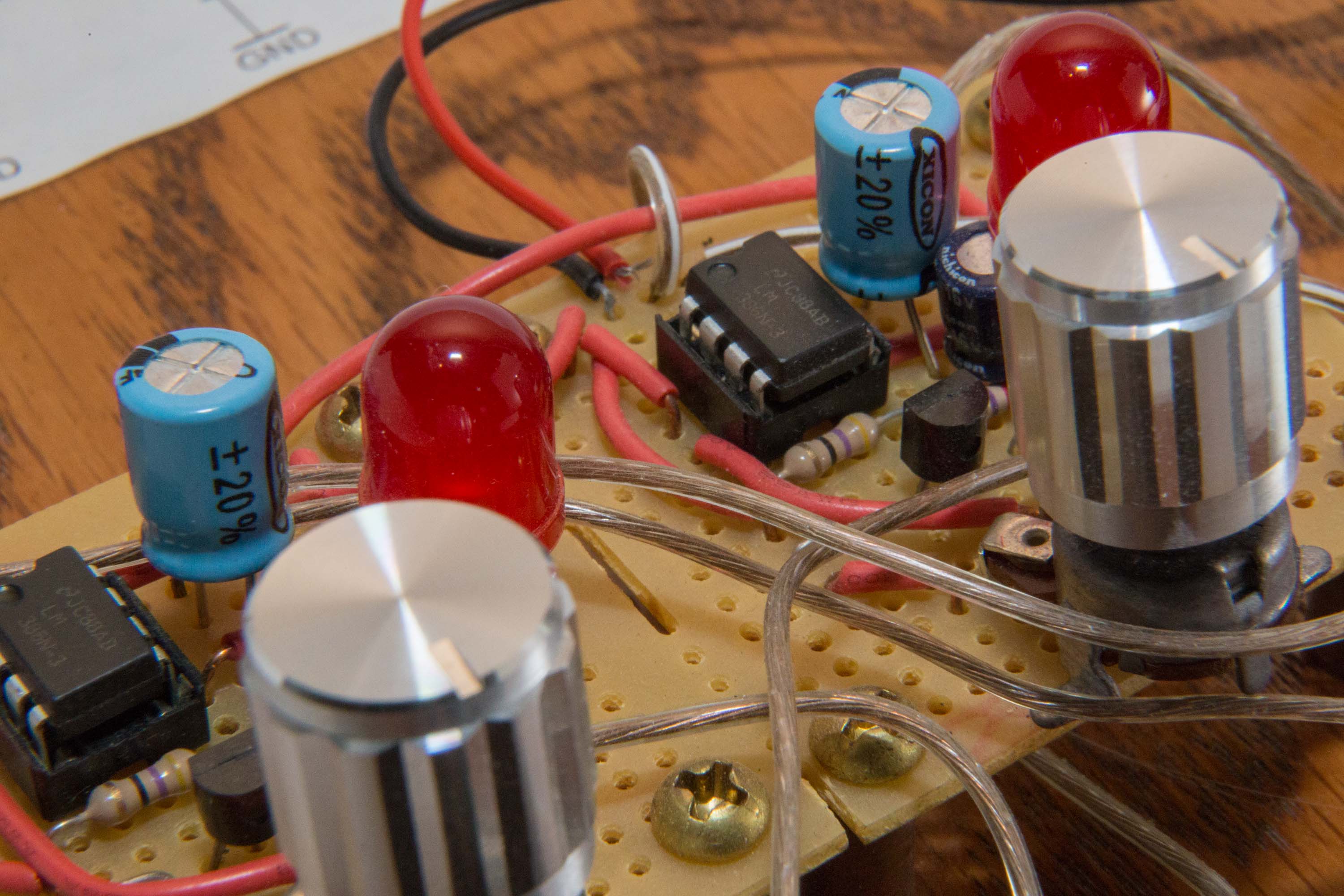
After I got the solderless breadboard version of the circuit working, it was time for putting it on a perf-board. First though, I needed a layout. I started drawing a layout but it always “flopped” because it wasn’t efficient enough, so my dad helped out. I guess I need more practice in designing efficient circuit layouts. I then had the task of bending all the components to the right shape and size. When this was done and they were all in the board, I soldered them all in. When all the pieces were in, I made all the solder bridges to complete the board. Now it was time for testing. I knew that it wouldn’t work the first time, so that’s what I was preparing myself for. But, to my surprise, everything worked perfectly the very first time!
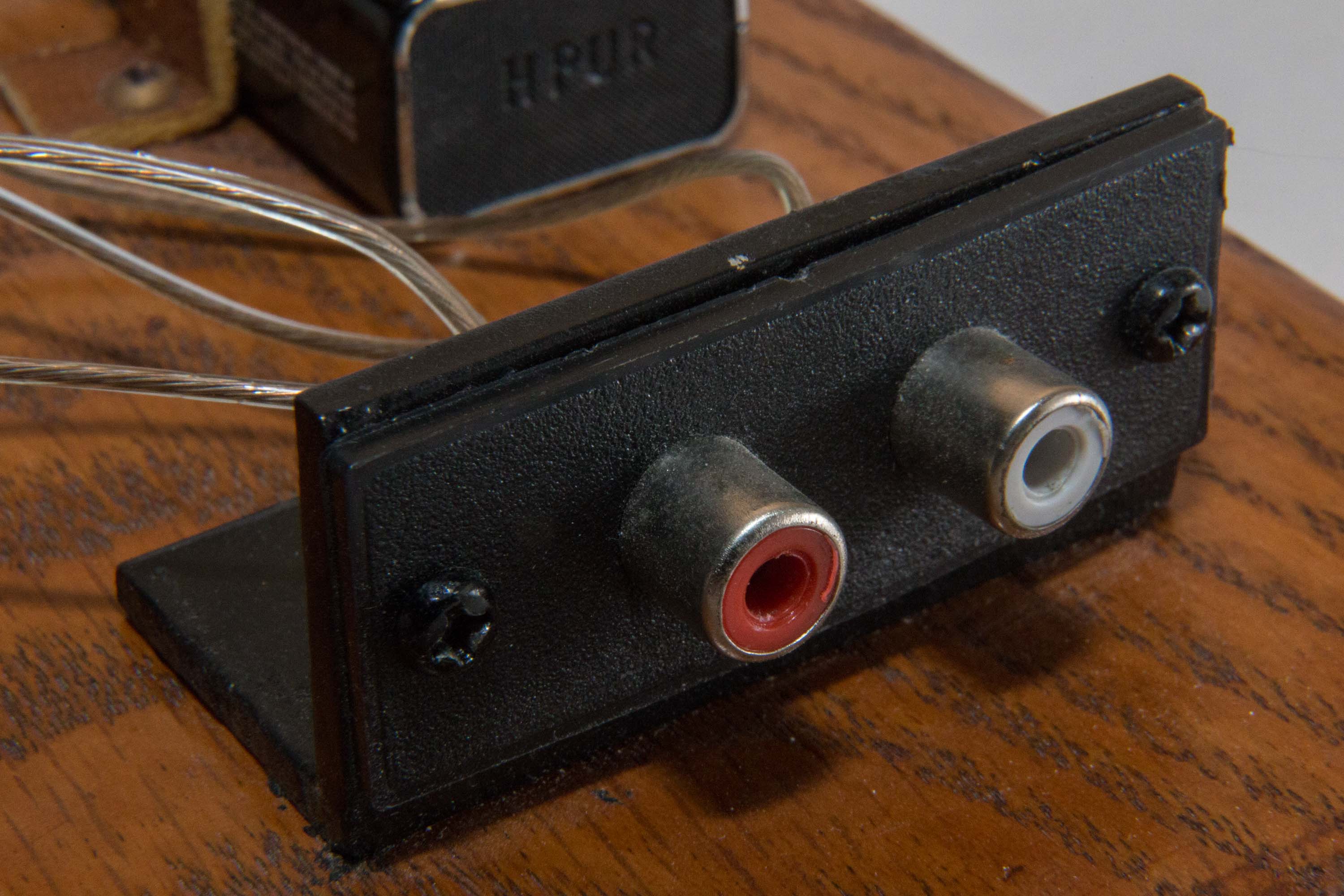
I only needed to mount the components to the board and draw up the circuit for the board top, to finally finish the project. I started all of this by getting some “L” braces and cutting them to fit the audio jack input and speaker outputs. Next, I painted the “L” braces, drilled some holes, and mounted them on the display board. Then I put in connectors and soldered them in. Finally, all that was left was to make the circuit schematic. The schematic wasn’t hard after I figured out the program. Finally, I was done!
What I Learned
This year in electricity, I learned that little tiny chips, when wired the right way, can produce amazing sounds for speakers. That got me thinking… Why the heck does everyone buy amplifiers? Why not make them? It’s not that hard, and it works very well. I think I’ll be making more of these little circuits for more speakers. I might never buy a real amp again. :)
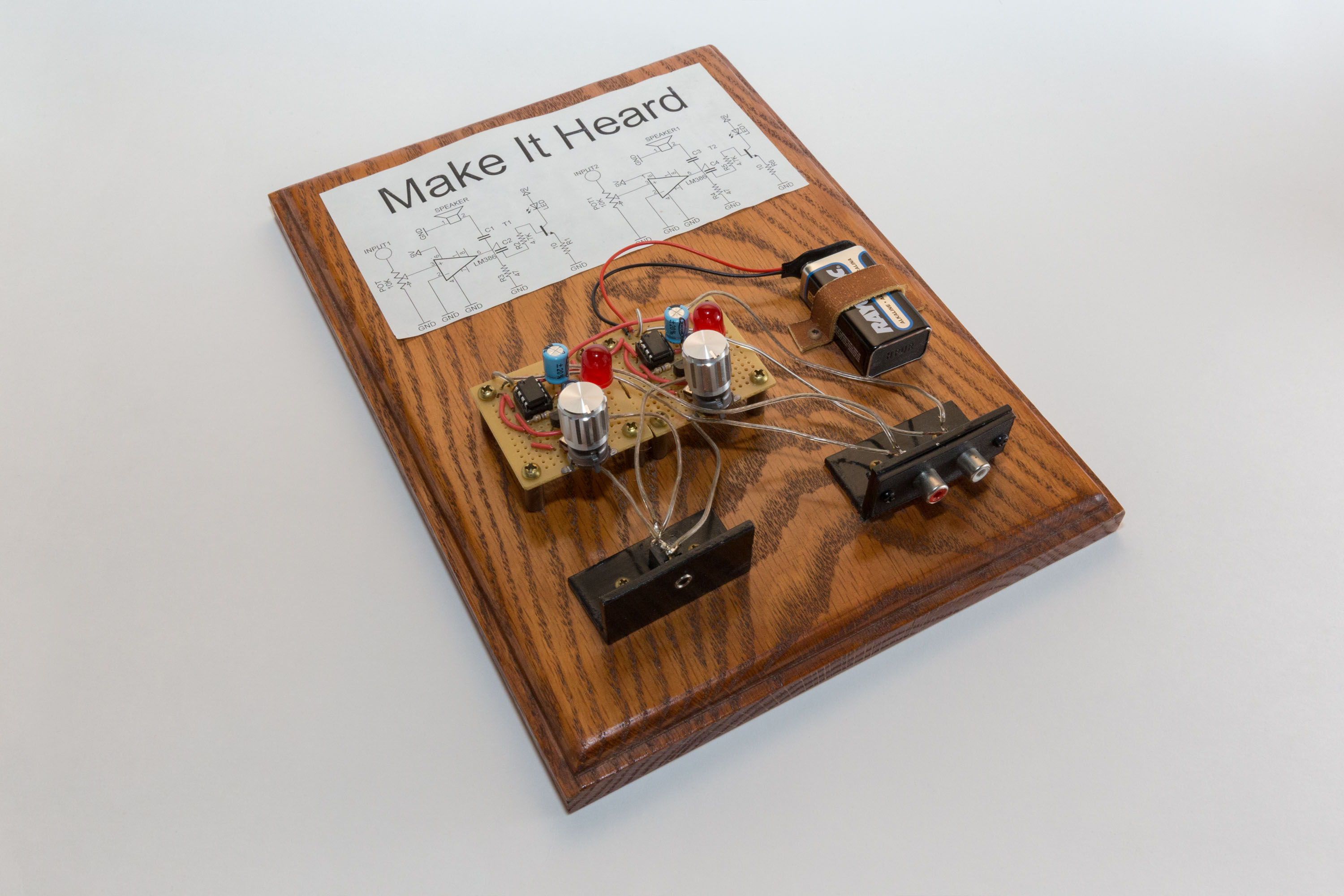
Pictures