

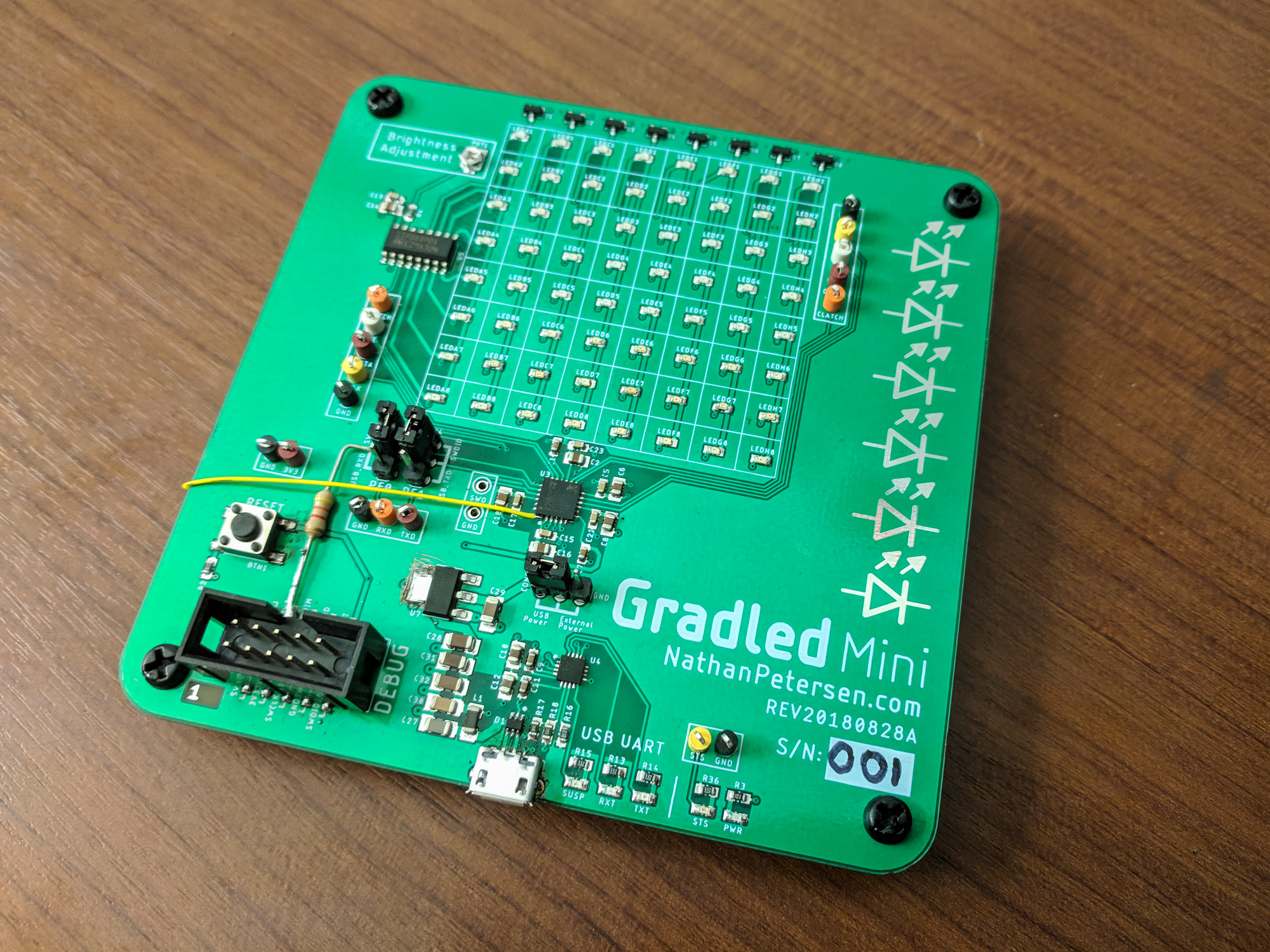
Gradled Mini: Prototype Modular Discrete LED Display
Background
This project came into being during my senior year of college at UW-Madison as a personal side venture. In May 2019, I complete my undergraduate schooling. It is not uncommon for students to decorate their graduation “hats” to personalize them and make them stand out in the crowd of graduates during the commencement ceremony. Typically, people create artwork related to the university they attended (i.e. UW-Madison) and use markers, glitter, little stickers, etc to create the decoration.

When it is my turn to partake in commencement, I also want to continue the hat-decorating tradition, but with a special twist: I want my hat to light-up and be able to show arbitrary artwork. Basically, I want to put an LED display on my head. I want a graduation LED hat. Thus, my Gradled project was born. (Pronounced: grad - led)
Project Requirements
After brainstorming what I wanted the end result to look like, I came up with a list of requirements for the project design phase:
- Cheap as possible (I didn’t want to shell out ~$100s just for my hat customization)
- Extendable to more than just graduation hat toppers (maybe wall art)
These generic requirements became specific requirements after more research:
- Single color, discrete LED matrix
- Tileable for arbitrary rectangular display configuration
- One PCB design that can be populated / configured for various paneling arrangements
- Low power consumption (i.e. powered from coin cell battery)
Design
LED Technology
The first step in designing this project was selecting the LED technology. There were basically two options to consider: discrete or serially addressable LEDs.
Discrete LEDs refer to “normal” LEDs; you apply a voltage across their terminals to light them up. These come in two flavors: single color or multicolor, with the multicolor ones essentially being multiple single color LEDs in the same package.
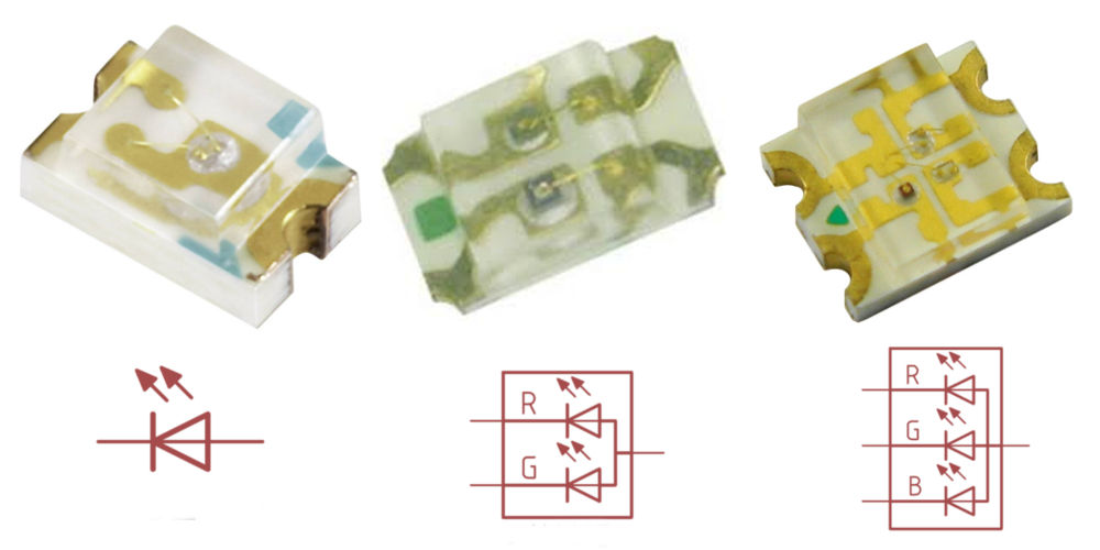
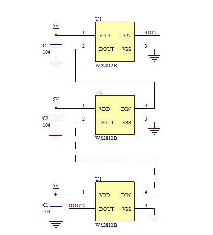
Serially addressable LEDs are “smart”; to control them, an MCU sends a serial stream of bits to their single DIN pin which tells them what color they should show. They are normally RGB. Importantly, they are chainable, meaning to control a chain of arbitrary length LEDs, the MCU only needs to interface with the first one. That LED then passes data along to the second, which passes data to the third, and so on.
Serially Addressable LEDs
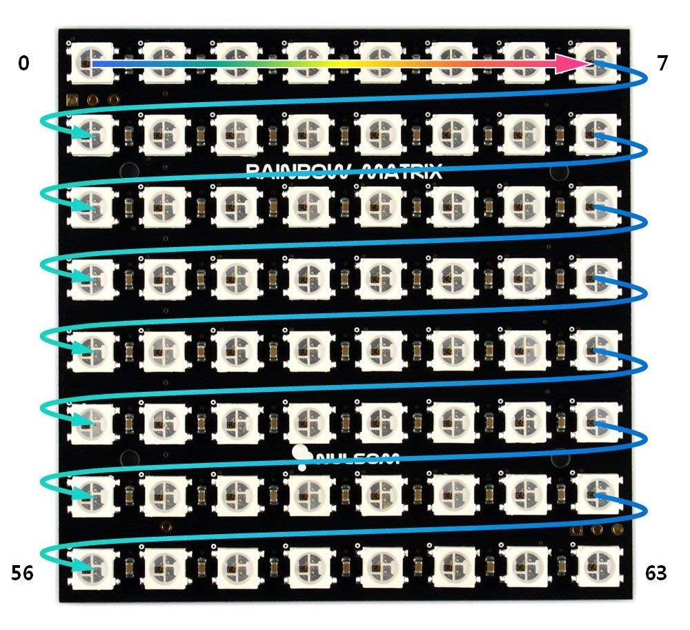
Both LED technologies can be used to create an LED matrix, with both having pros and cons. Using serially addressable LEDs to create a matrix is more intuitive: simply arrange a long chain of LEDs into a zig-zag pattern (see picture below).
Pros of serially addressable LED matrix:
- Easy to understand
- Easy layout on circuit board (only one signal trace goes from LED to LED)
- Final matrix size can be arbitrary at design time: only constraint is where the “fold” of the chain occurs
- Connecting multiple PCBs together to form a larger display only requires one data pin to cross the PCB boundary
Cons of serially addressable LED matrix:
- Each LED is expensive compared to simple discrete LEDs
- High maximum power consumption as all LEDs can be on at once
- Limited refresh rate because data flows through all LEDs at fixed rate
Discrete LEDs
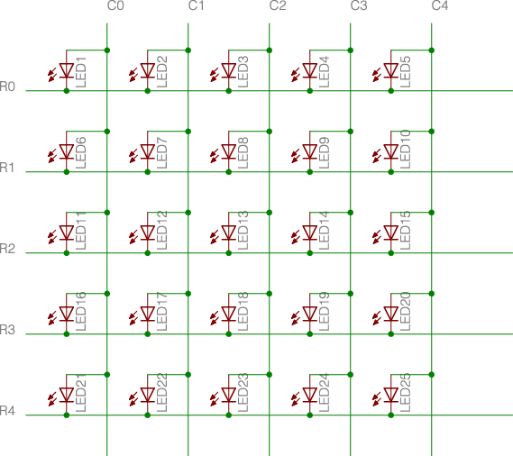
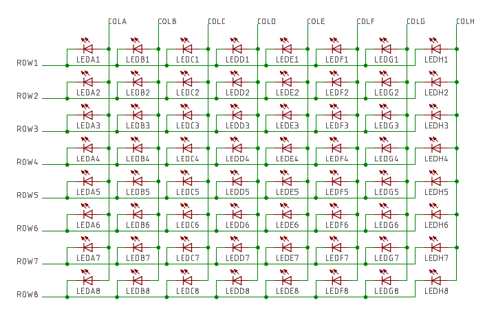
Using discrete LEDs instead of serially addressable LEDs is also an option. For this to work, the LEDs are connected via rows and columns, as shown in the circuit diagram below. To display patterns, each column is time multiplexed, meaning that only one column of LEDs is active at any given time. Due to persistence of vision, our eyes perceive the whole panel as active. This design requires row and column driving circuitry to enable the desired LEDs.
Pros of discrete LED matrix:
- Very cheap (each LED is a order of magnitude cheaper than serially addressable variant)
- Low maximum power consumption due to column multiplexing
- Faster refresh rate
Cons of discrete LED matrix:
- Not as intuitive; more complex firmware
- Requires constant control to maintain whole display pattern
- Many more traces to route on PCB
- Many more signals need to cross between PCBs to form larger displays
As described, the pros of one technology are the cons of the other, and vise versa. The biggest limiting factor, which ended up making the decision between the two, is the sheer cost difference between the two choices: For 1,000 LEDs, discrete LEDs cost ~$6 total, while serially addressable LEDs cost ~$60 total. Because of this, I went with discrete LEDs. (Not really a fair comparison: 0603 red LEDs versus 5050 WS2811B RGB LEDs…)
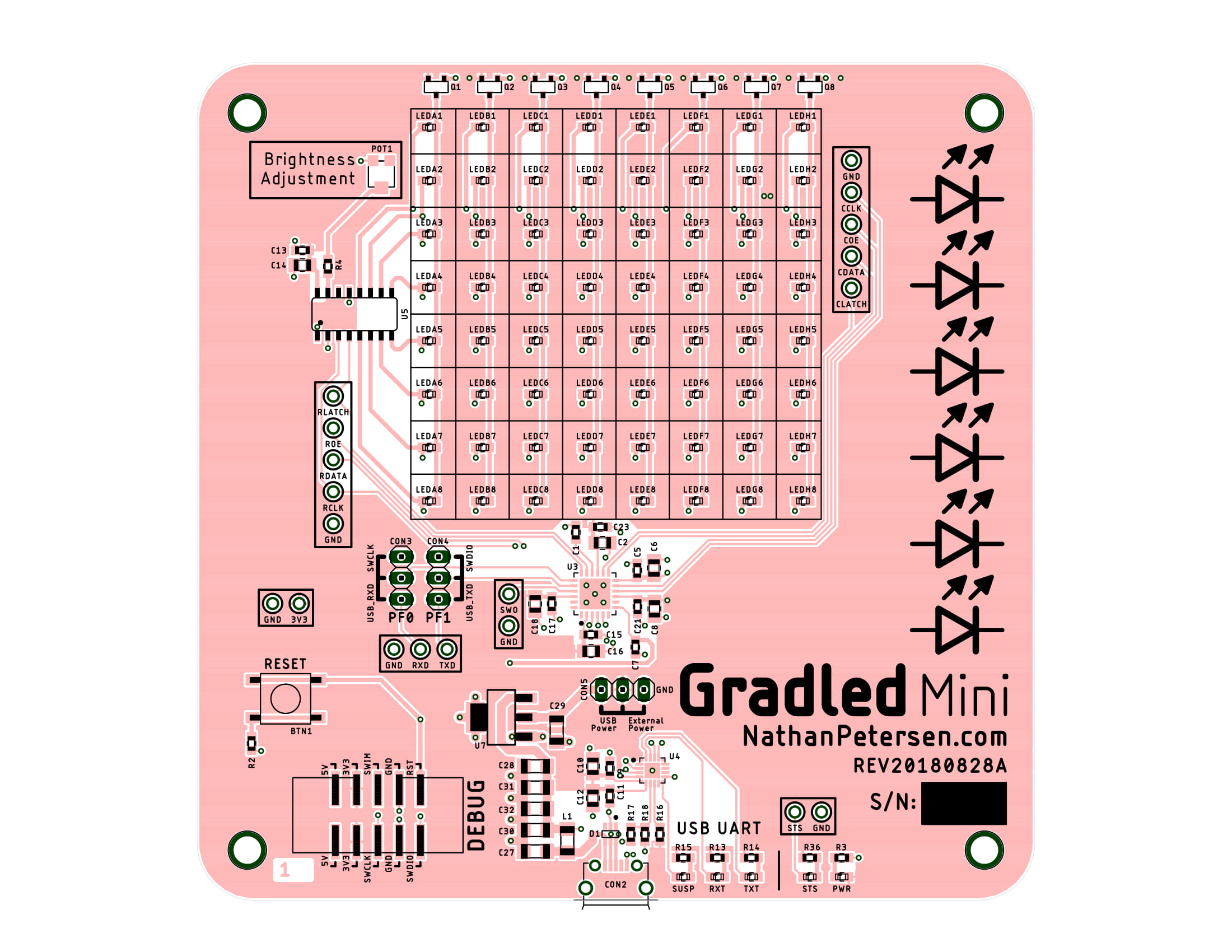
Schematics
Since the whole purpose of Gradled Mini is to prove the design for the final Gradled project, the schematics need to be as close as possible to final implementation. This means that the LED driving circuitry needs to be the same as the final PCB.
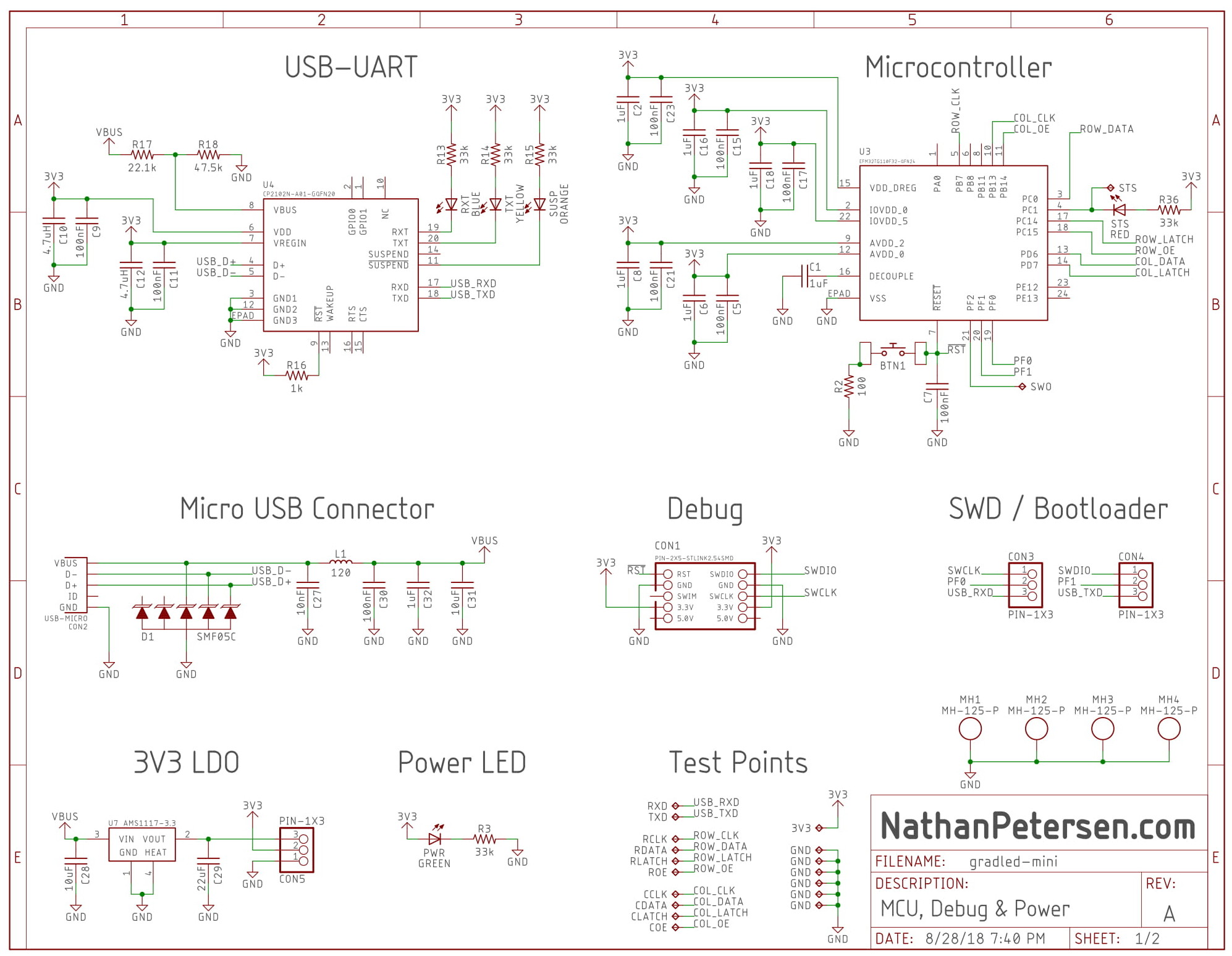
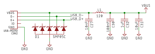
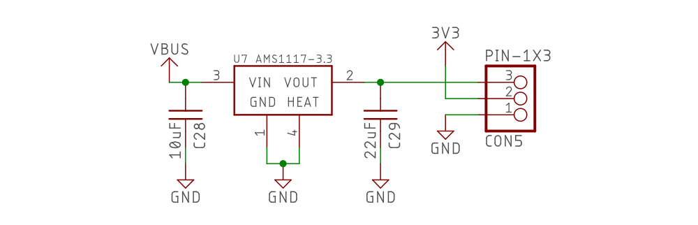
USB Power
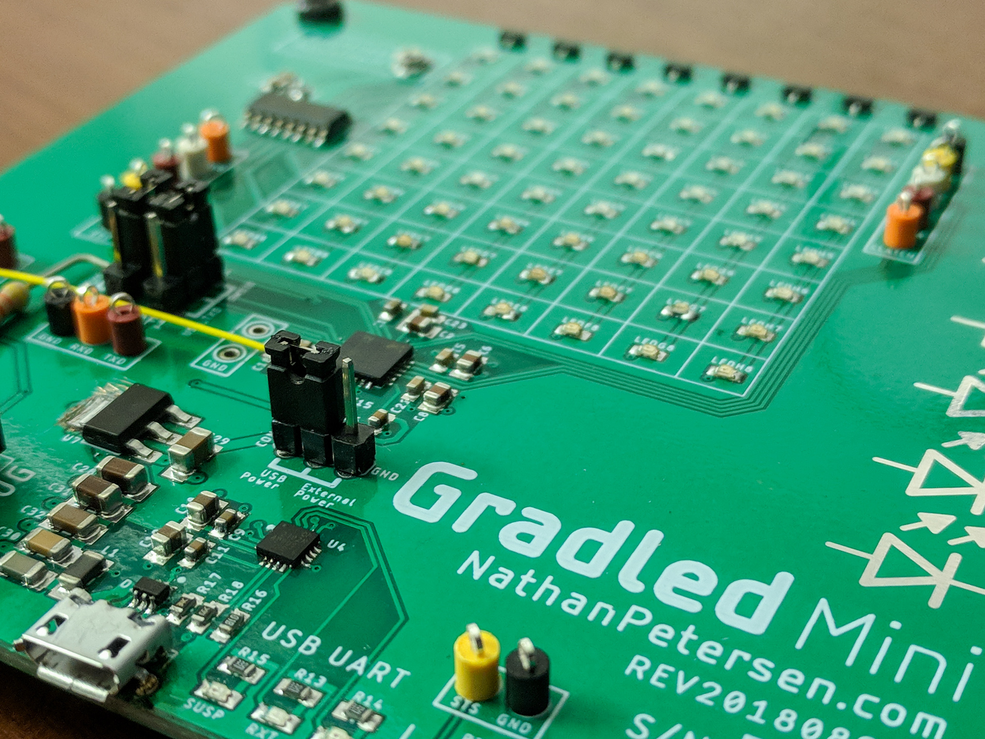
This test board is powered from a micro USB port. The 5V bus voltage is filtered and then brought down to 3.3V using an LDO.
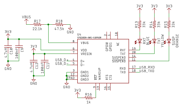
USB-UART
In an attempt to use the factory-programmed bootloader on the Silicon Labs MCU, a USB-UART IC was included to provide a serial interface with the MCU.
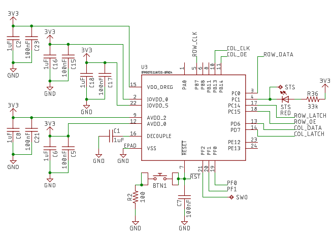
Microcontroller
Since I interned with Silicon Labs for two summers, I really wanted to use one of their MCUs for this project. I decided on a small and simple Tiny Gecko (EFM32TG110F32), which has an ARM Cortex-M3 core inside.
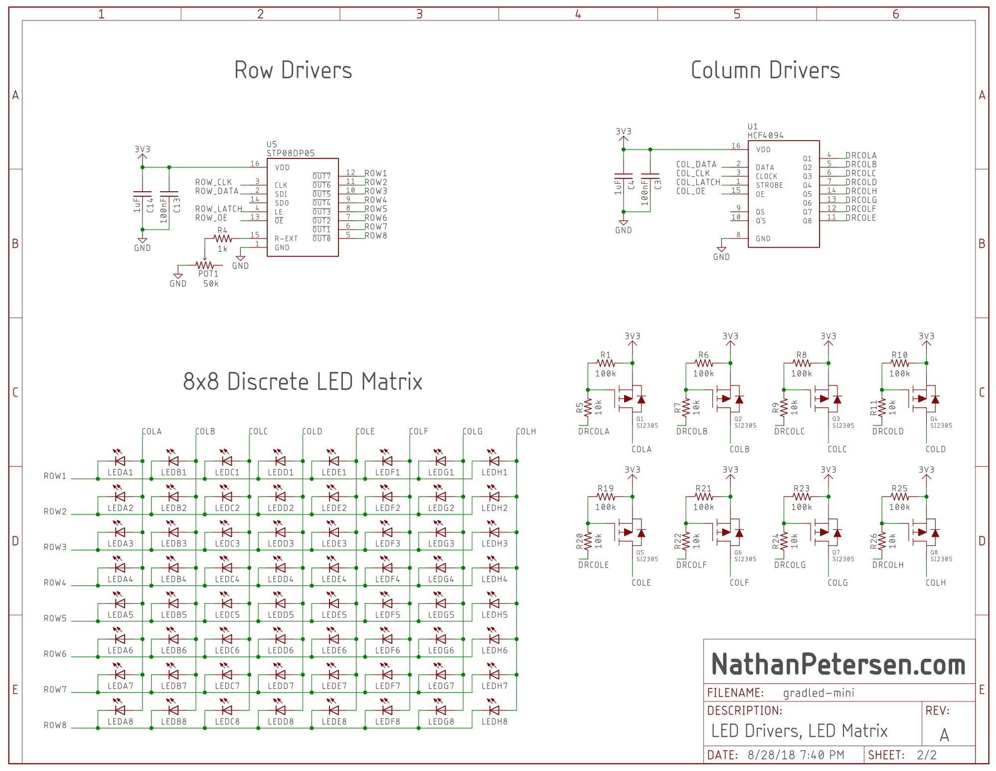
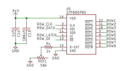
Row Driver
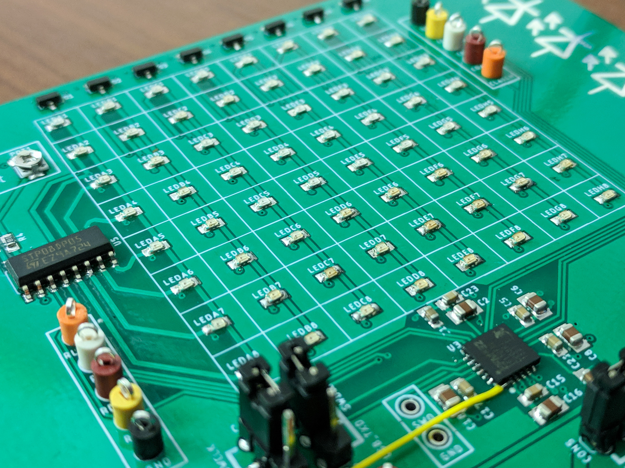
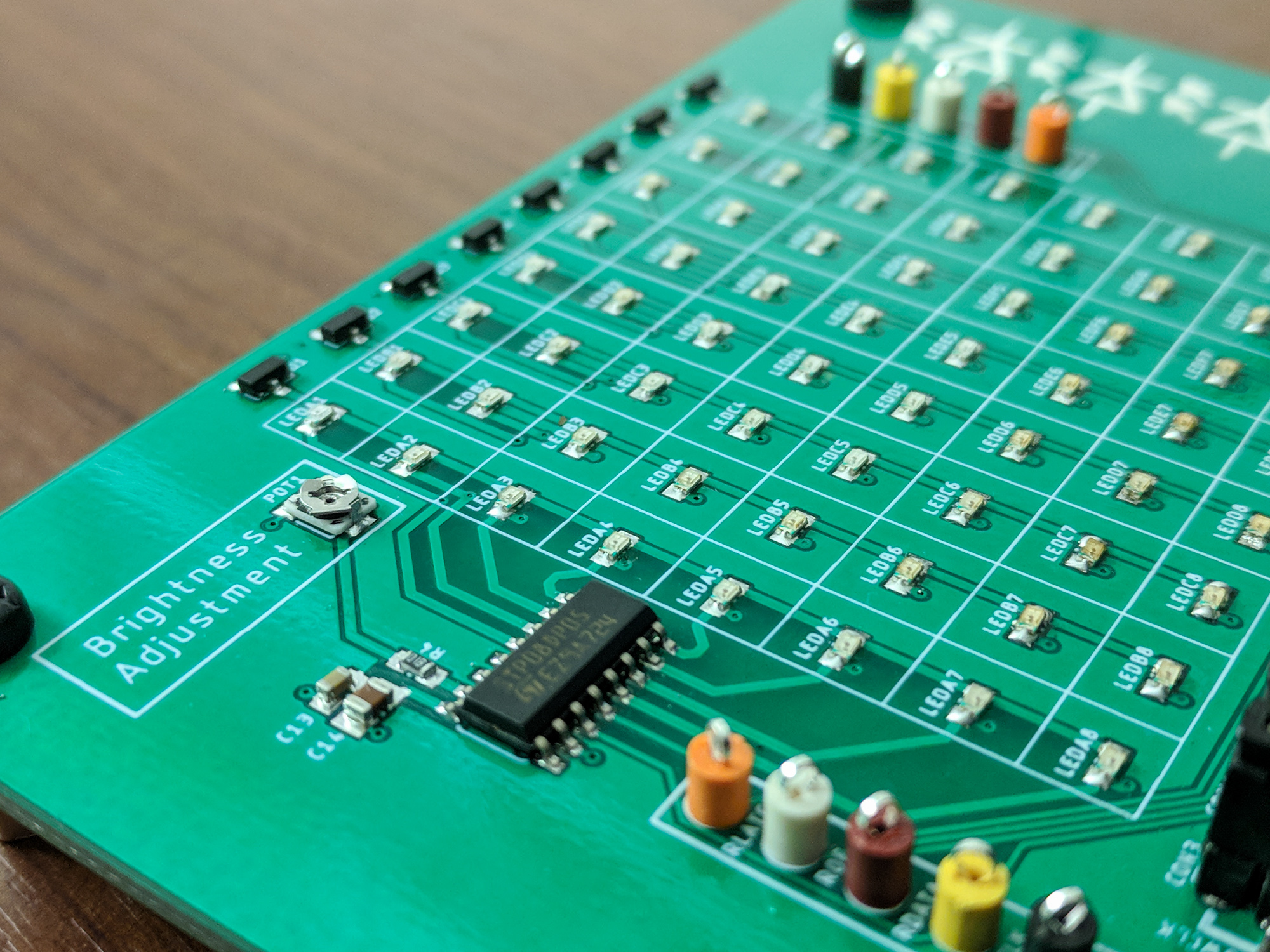
The row driver needs to sink a constant amount of current per channel. This controls LED brightness. I have used a MBI5024 before, which is a 16-bit clone of other common LED driver IC’s, such as ST’s STP08DP05. The resistance between pin 15 (R-EXT) and ground determines how much current can flow per channel, thus controlling LED brightness.
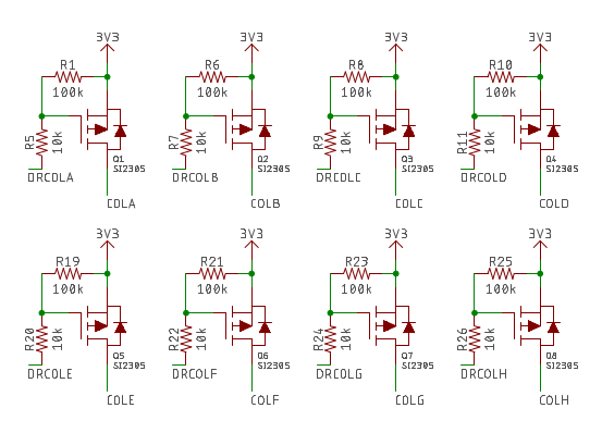
Column Driver
The column driver is effectively a high-side switch, meaning it can connect devices directly to power or not. A P-channel MOSFET is used to do this switching (sourcing up to ~100mA each), and a shift register is used to create the serial interface for the MCU.
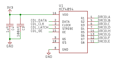
LED Matrix
As described earlier, a matrix of discrete LEDs is used. For each column, all LED anodes are connected together, and for each row, all LED cathodes are connected together.
Hardware
The physical design of this PCB wasn’t critical since it was a test board for proving the design worked. However, the LED pitch was chosen to match the final version PCB LED pitch.
LED Pitch
To support each individual PCB panel being tiled to create a larger display, the LED pitch needs to be carefully considered to prevent obvious discontinuities between panels.
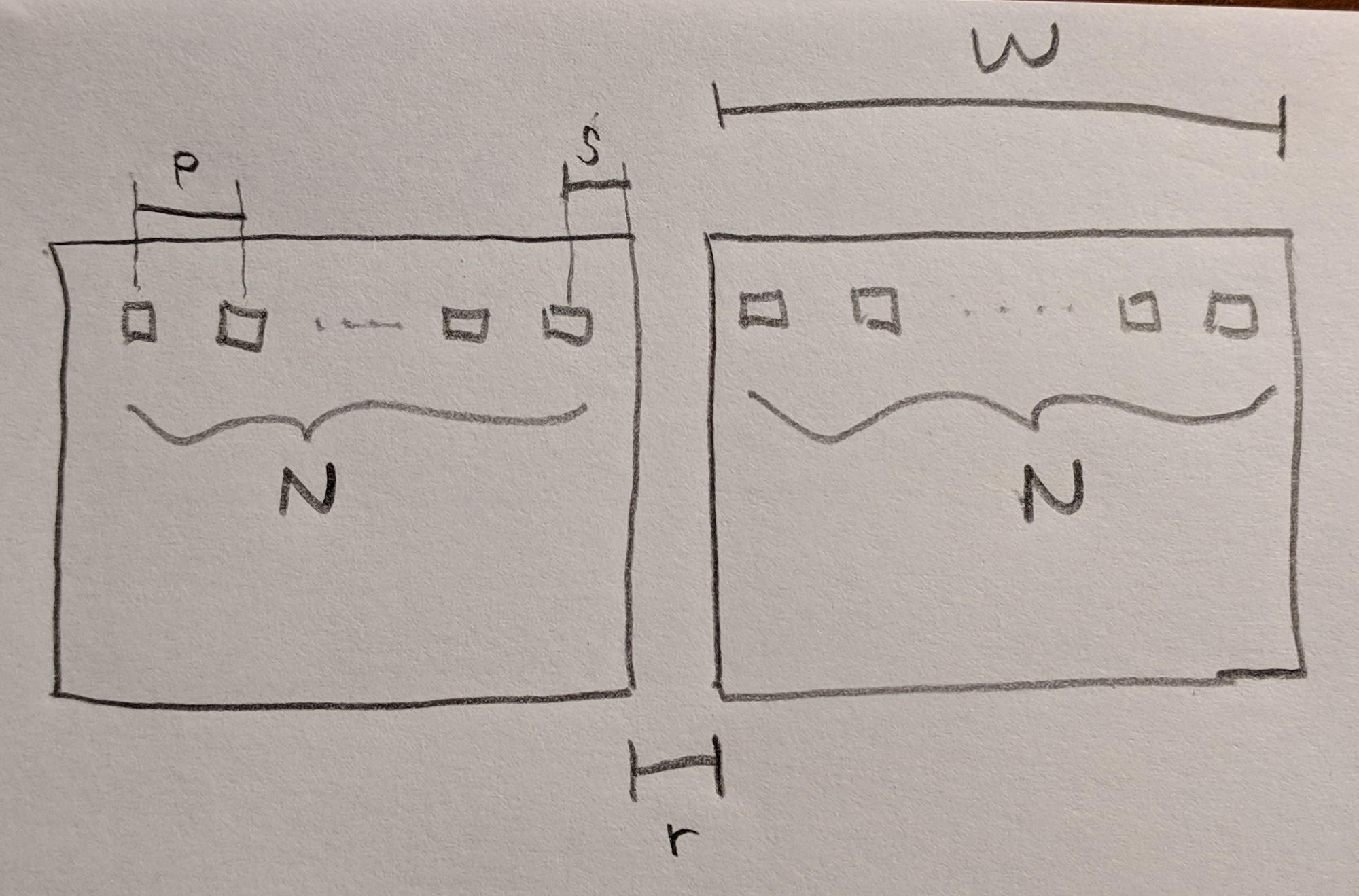
The following two equations govern the LED pitch $p$ and distance from edge of board $s$, given the PCB width $W$, panel spacing $r$, and number of LEDs per row $N$. The first relates panel spacing to pitch, and the second accounts for all distance across two panels.
$$ p = r + 2s $$
$$ 2W + r = r + 4s + 2(N-1)p $$
Solving for pitch $p$ and distance from edge of board $s$:
$$ p = r + \frac{W}{N} - \frac{r(N-1)}{N} $$
$$ s = \frac{W}{2N} - \frac{r(N-1)}{2N} $$
This means that for a 10cm by 10cm PCB with 2mm panel spacing and 16x16 LEDs per panel, the LED pitch and distance from edge of board is the following.
Let $W = 100mm$, $r = 2mm$, and $N = 16$.
Then $p = 6.375mm$ and $s = 2.1875mm$.
For a fixed size PCB and panel spacing, varying the number of LEDs changes the LED pitch and distance from edge of board (r, W, p, s in mm; N is # of LEDs per side):
| r | N | W | p | s |
|---|---|---|---|---|
| 2 | 16 | 100 | 6.375 | 2.1875 |
| 2 | 18 | 100 | 5.667 | 1.8333 |
| 2 | 20 | 100 | 5.100 | 1.5500 |
| 2 | 22 | 100 | 4.636 | 1.3182 |
| 2 | 24 | 100 | 4.250 | 1.1250 |
| 2 | 25 | 100 | 4.080 | 1.0400 |
| 2 | 30 | 100 | 3.400 | 0.7000 |
| 2 | 32 | 100 | 3.188 | 0.5938 |
PCB
The PCB was designed for easy manufacturing anywhere, so design rules used 6/6mil spacing and 0.3mm minimum drills in a 10cm x 10cm board.
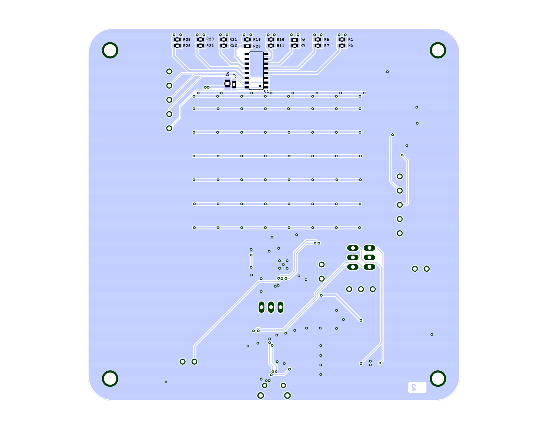
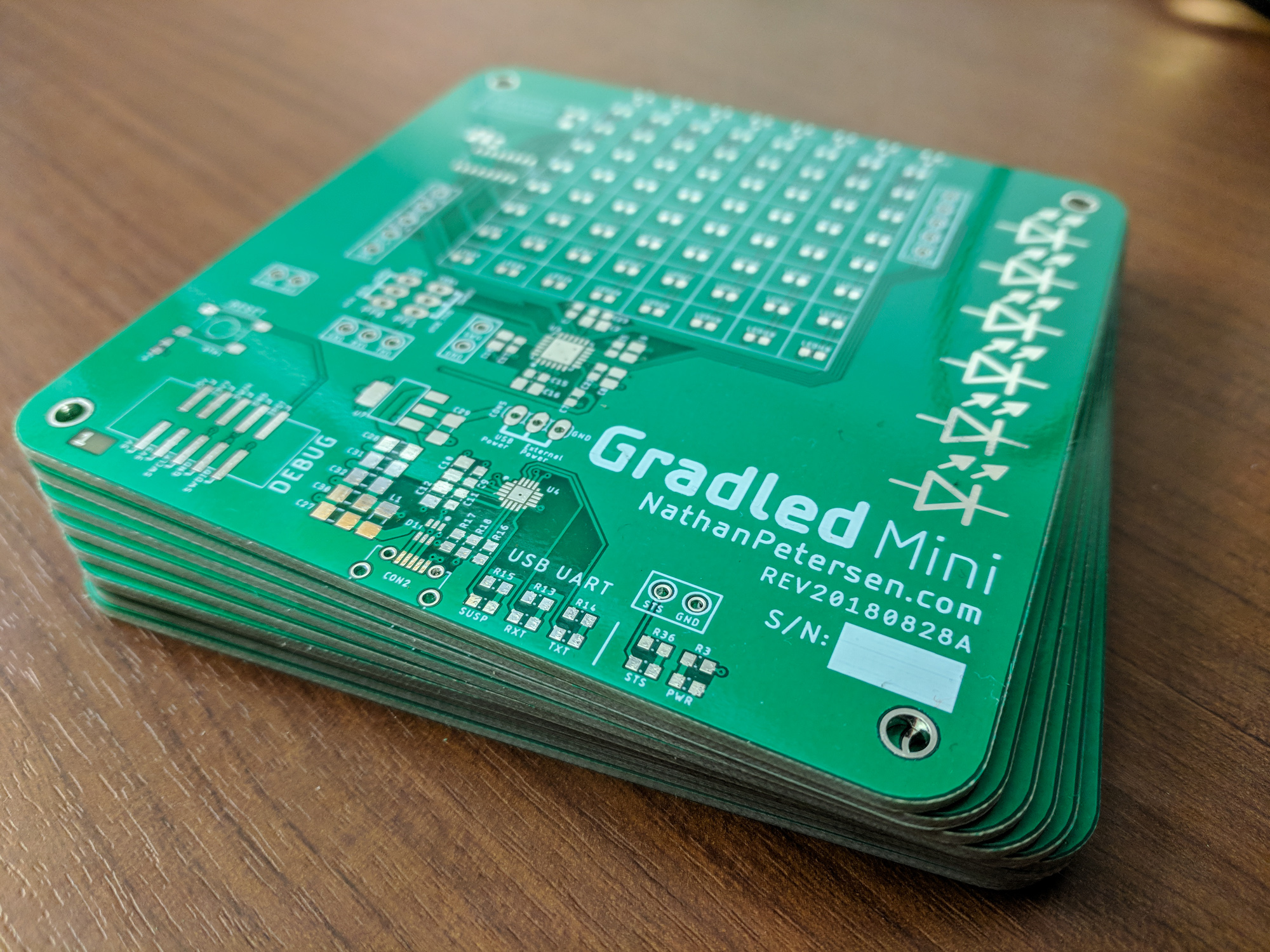
Seeed Studio
Seeed Studio (www.seeedstudio.com) manufactured the PCB using their Fusion PCB service. The returned boards worked just as expected, with no issues. Read my previous posts about them here and here.
Firmware
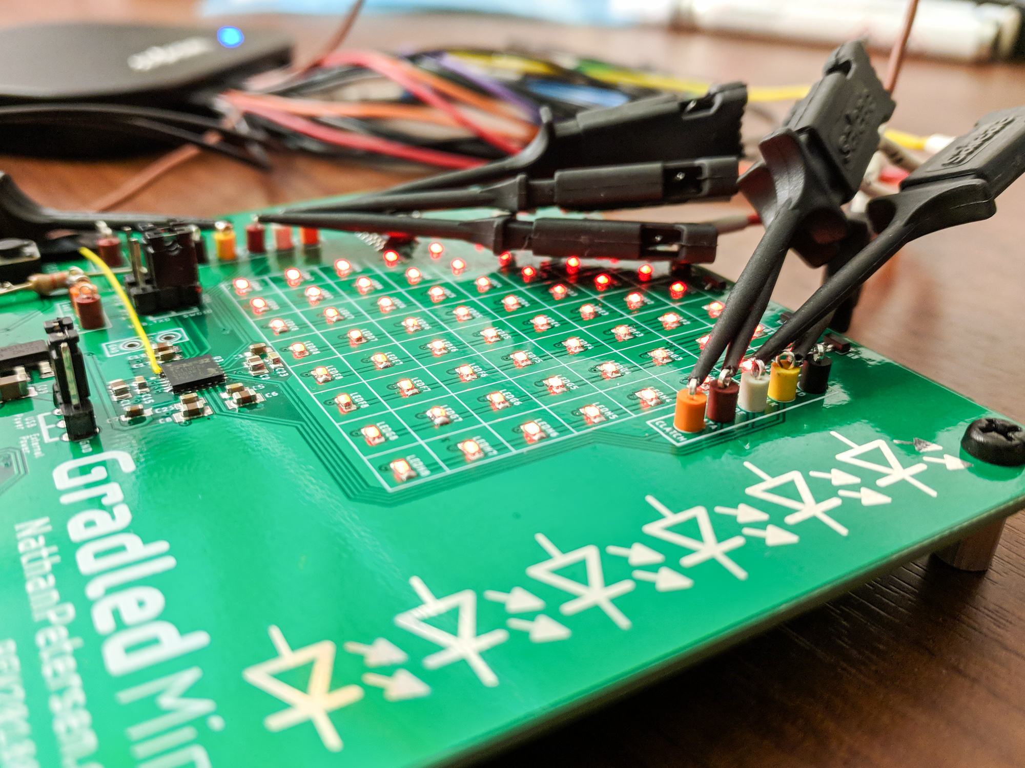
Normally, getting the first board off the ground and doing good things is a time-consuming, frustrating process. For all the past projects I’ve made, I didn’t own any debugging tools, like logic analyzers or an oscilloscope. I got pretty good at using the status LED on my board to debug all the problems that arose.
For this project, two serial data buses are used to communicate with the column driver and row driver. The MCU rotates through the columns and displays each column separately. The high refresh rate, combined with the persistence of vision effect, makes it look like all the columns are on at once.
This multi-bus interface, operating in synchronization with each other and with tight timing requirements, could have been quite the challenge to get working.
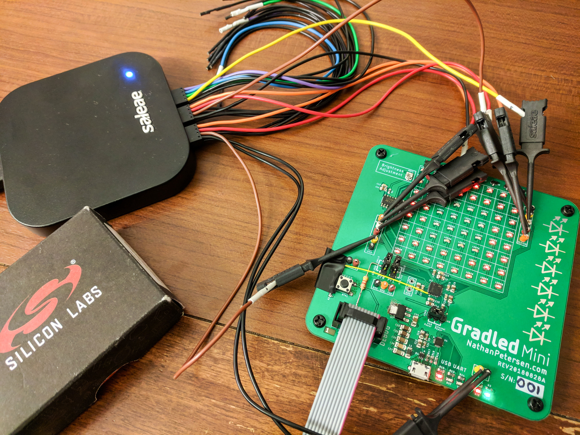
Saleae Logic Analyzer
I decided to take the plunge and buy a Saleae Logic Analyzer (www.saleae.com) to help me debug projects and improve time for initial hardware bring up. This has proved to be practically invaluable for helping solve issues such as clock frequency configuration, timer configuration, etc.
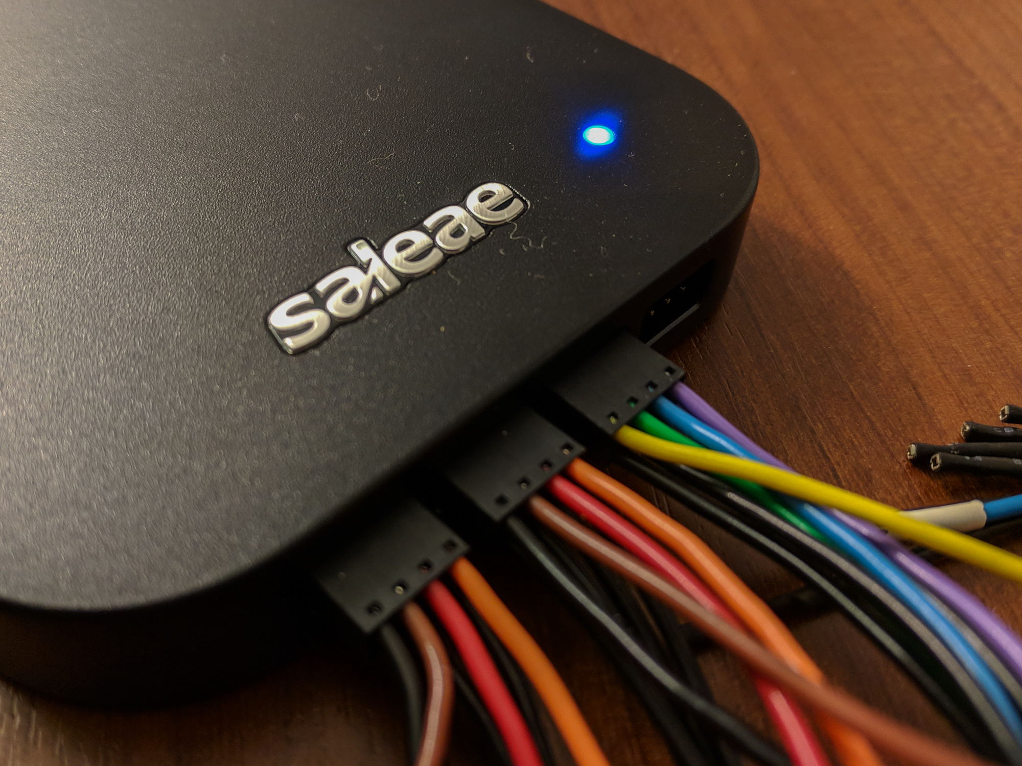
With test equipment, I can write some code, flash the MCU, and immediately see if the code works. This is huge. Embedded systems are very picky about details being correct, so any error can bring down the entire system. The most frustrating problems can easily be identified and fixed by simply having the ability to see the waveforms.
Column / Row Drivers
To control this multiplexed LED display, the firmware needs to turn on each column of LEDs individually. By cycling through the columns at a high enough rate, a persistence of vision (POV) effect is achieved, making the display look static.
Since the column drivers source current and the row drivers sink current, we can treat them like simple switches. To turn on any arbitrary LED, the firmware must close the column driver switch of that LED, which connects its anode to the power source. Then, the firmware needs to close the row driver switch for the LED, which connects its cathode to ground, allowing current to flow and illuminating the LED.
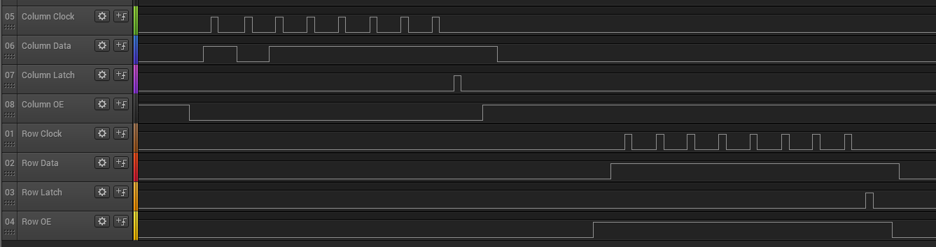
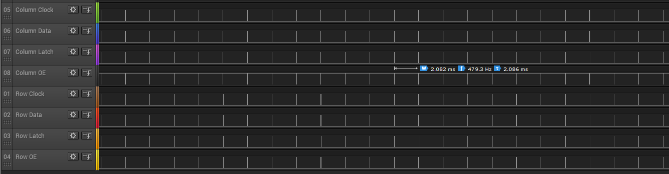
By design, both column and row drivers have a similar interface to the MCU: a SPI-like bus. The MCU needs to generate the appropriate waveforms on the clock, data, latch and output enable pins to set up the drivers. First, the column driver is configured, followed by the row driver, as seen in the image below.
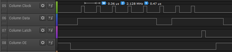
The data bits are shifted out of the MCU at approximately 2MHz, as seen below.
Testing
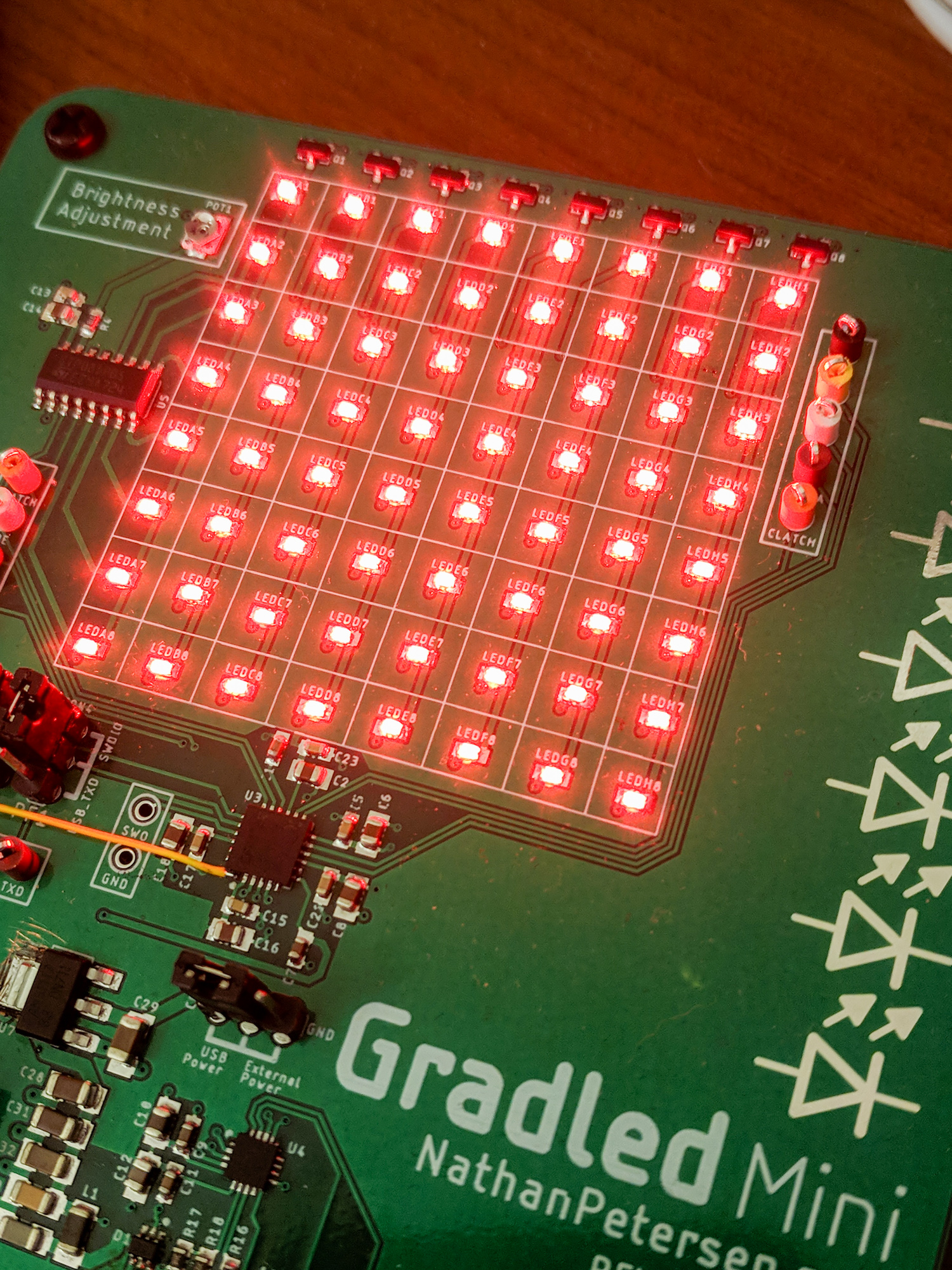
The point of making this prototype board was to see if LED driving technology worked like it was supposed to work. Basically, to prove current consumption is low.
LED Current Consumption
I made a simple animation for testing the display that looks like the GIF below. It starts with all LEDs off, then makes a square of LEDs on the display’s perimeter. It then makes progressively smaller squares around the perimeter of the display, turning more and more LEDs on per frame. After all LEDs are on, it starts over.
I then put a current sense resistor $R_{sense} = 10.2\Omega$ inline with the board power supply so I could measure current consumption. I used an oscilloscope to record voltage across the resistor during an animation cycle. From the data, I know precisely how much current is consumed.
Maximum Current
Looking at the display, it appears like all the LEDs can be on at once, thus maximum current is current through each LED x total number of LEDs. But, the whole reason for designing this time-multiplexed matrix topology was to reduce current consumption. Therefore, we expect the maximum current at any time to be the current through one column, or 8 x each LED’s current.
Current Per LED
We investigate current per LED using two approaches: from measurements on oscilloscope during animations, and via theoretical equations from LED driver datasheet. If these agree, we can be confident that overall system performance matches expectations.
Via Oscilloscope
During the animation cycle when all LEDs are on, LED current is the difference between total current and steady state current (MCU, etc), see equation below. Thus, to find each LED’s consumption, we need to measure steady state current consumption when no LEDs are on, and total current when all LEDs are on.
$$ I_{LEDs} = I_{total} - I_{ss} $$
Total Current
$$ I_{total} = \frac{854mV}{R_{sense}} = 83.73mA $$
Steady State Current

$$ I_{ss} = \frac{150mV}{R_{sense}} = 14.71mA $$
Per LED Current
Because there are 8 LEDs per column, we can calculate current per LED:
$$ I_{LED} = \frac{1}{8} (I_{total} - I_{ss}) $$
$$ I_{LED} = 8.63mA $$
Via LED Driver Datasheet
The LED driver we are using is a constant current sink LED driver. Its datasheet doesn’t give an equation relating current sink vs. external resistance, but other clones do. For example, the MBI5024 provides our equation of interest. By setting one external resistor $R_{ext}$, we can control the current on all LED channels.
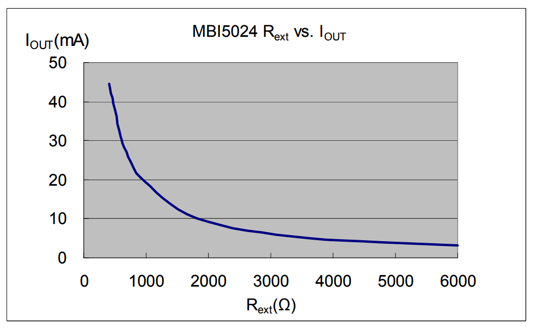
The datasheet provides an equation to convert this resistance, $R_{ext}$, to a current, $I_{channel}$ (see page 12 of datasheet).
$$ I_{channel} = 1.24V * \frac{1}{R_{ext}}*15 $$
We measure $R_{ext} = 2.177k\Omega$, and calculate $I_{channel} = 8.544mA$.
Analysis
Both methods for determining current per LED result in very close answers, only differing by about 1%. In summary, we can confidently say that the maximum current is the sum of steady state current and current for one column:
$$ I_{max} = I_{ss} + I_{column} $$
$$ I_{max} = 14.71mA + (8 * 8.63mA) $$
$$ I_{max} = 83.73mA $$
With a CR2032 coin cell battery (rated at 225mAh) as the power source, this display can run for at least $\frac{225mAh}{83.73mA} = 2.7 hours$.
Animation Timing
The test animation, as described in detail above, is configured to add a new square three times per second, thus each animation frame lasts 333ms. To perform the column multiplexing, the firmware is configured to cycle through updating each column at a rate such that individually, each column is updated at 60Hz to prevent flickering.
We can verify these constraints by looking at two things:
- Saleae Logic Analyzer data for serial interface to column / row drivers
- Oscilloscope current waveform data
Serial Interface Observations
Since the column and row drivers need to be updated for each column update, we can measure their update frequency. This value should be 8 x 60Hz, if each column is refreshed individually at 60Hz. The plot below confirms this: the OE (output enable) pin is toggled at 480Hz, which precisely matches our expectations.
Current Waveform Observations
By looking at the board current consumption waveform, we can deduce the timing realized by the firmware.
Animation Frame Update Rate
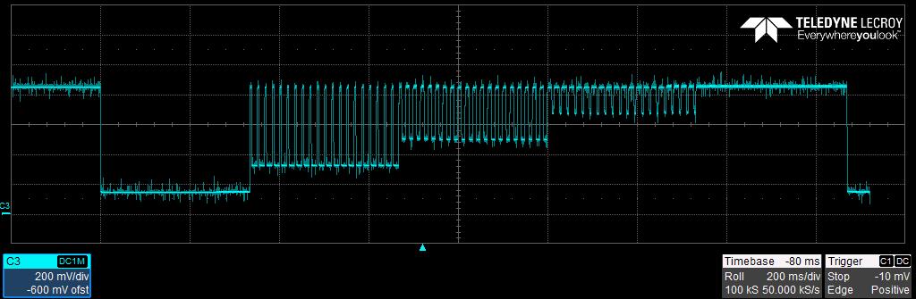
The floor of the current waveform increases throughout the animation, which makes sense because more and more LEDs remain on.
Each time the floor increases, a new animation frame is displayed. This means that we can calculate the animation update rate as the time between floor increases. In the animation below, this is measured to be precisely 333ms, as expected.
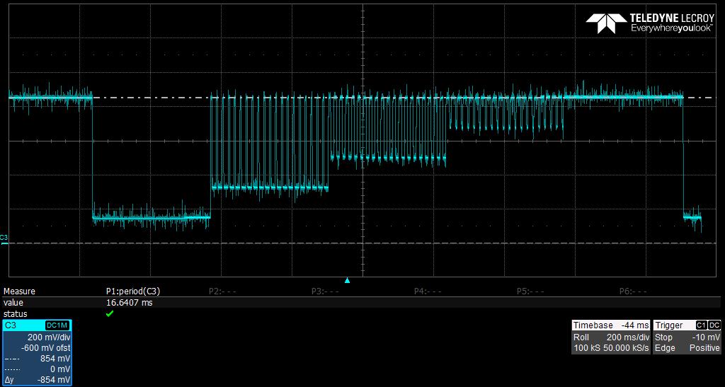
Column Update Rate
If we focus on the first animation frame when only the outer LEDs are illuminated, we can reason that the current should be maximum for 1/4 of the total time since there are eight columns and only two are on. This is exactly what the animation below shows. The period of the waveform is 16.6ms resulting in our expected 60Hz update rate per column. The current maximum lasts for 4ms, which also matches our expectation of being one quarter of the period.
Mistakes
The goal of this project was to prove that the design worked, giving confidence that the first go around at the final Gradled board would work. This was mostly a success, although a few minor issues arose.
My 3.3V LDO footprint was wrong. Turns out the heat sink tab is connected to $V_{out}$, not ground.
I also never figured out how to use the factory-burned bootloader on the MCU to load in new program images. The USB-UART IC worked a treat: its status LEDs worked just as expected. When I plugged it into my computer, it came out of suspension and was ready for communication. Unfortunately, I never could flash the MCU using UART.
Lastly, the routing for the column driver can be improved. I swapped pins to ease trace routing, and figured that I could simply correct for the change in firmware. While I did get this to work, if the pins were in order, I could simply toggle the clock line to activate the next column over. Currently, I must send out all new data for each column. This creates a slight overhead during the ISR which updates the display.
Future
Obviously the next step is to design and build the full version! I graduate in May 2019, so I have a full semester to get it up and running. Since I took the time to build this prototype, it should be fairly easy to get it working. Fingers crossed.
Also, I would like to extend this idea to discrete RGB LEDs. Basically, this means that each LED becomes three (in the same package). This should be a natural extension of this design. Perhaps I will get around to this after graduation.
Finally, it would be very nice to be able to control the display using Bluetooth from a phone. This doesn’t change the display itself, but just adds another subsystem and makes the firmware more complex. Should be doable.
Summary
This project went about as planned. I proved that my circuitry for driving an LED matrix works as expected, and built up preliminary firmware for future displays. I also learned how to use the Saleae Logic Analyzer to aid in firmware development, and calculated a lower bound on the time this display can run off of a given battery.
Picture Gallery
Extra pictures of Gradled Mini for your browsing pleasure. :)
New Post Notifications
If you read this far into this article, you might be interested in subscribing for email notifications about future new posts I write. I will never spam you! Every few months, I write a new article for this website, and will send you email about it. You can unsubscribe at any time. Thank you.