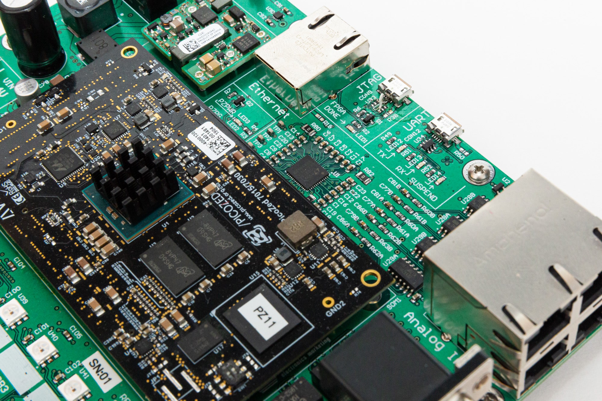
AMDC REV D Hardware
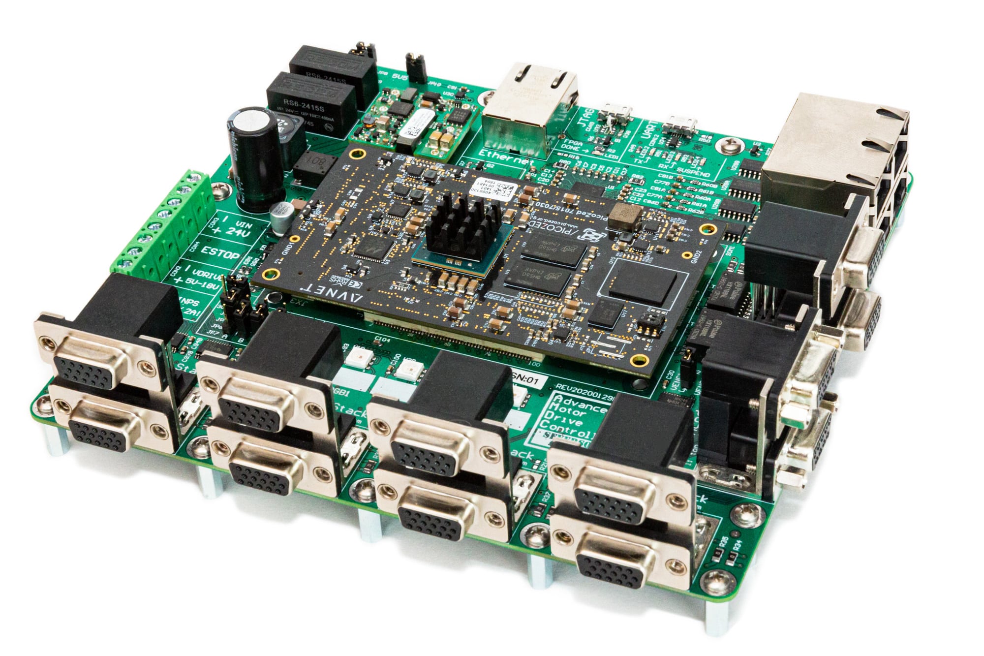
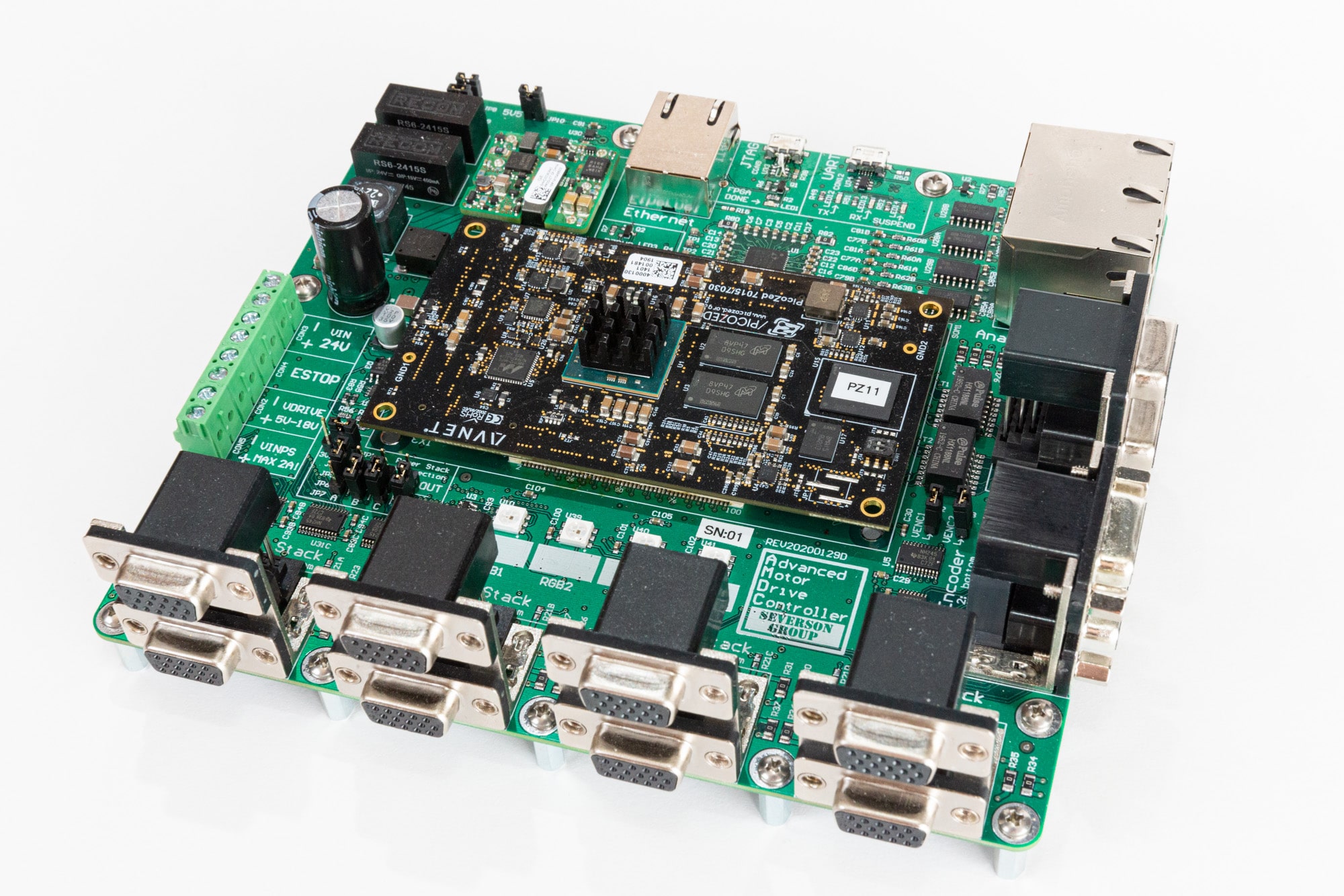
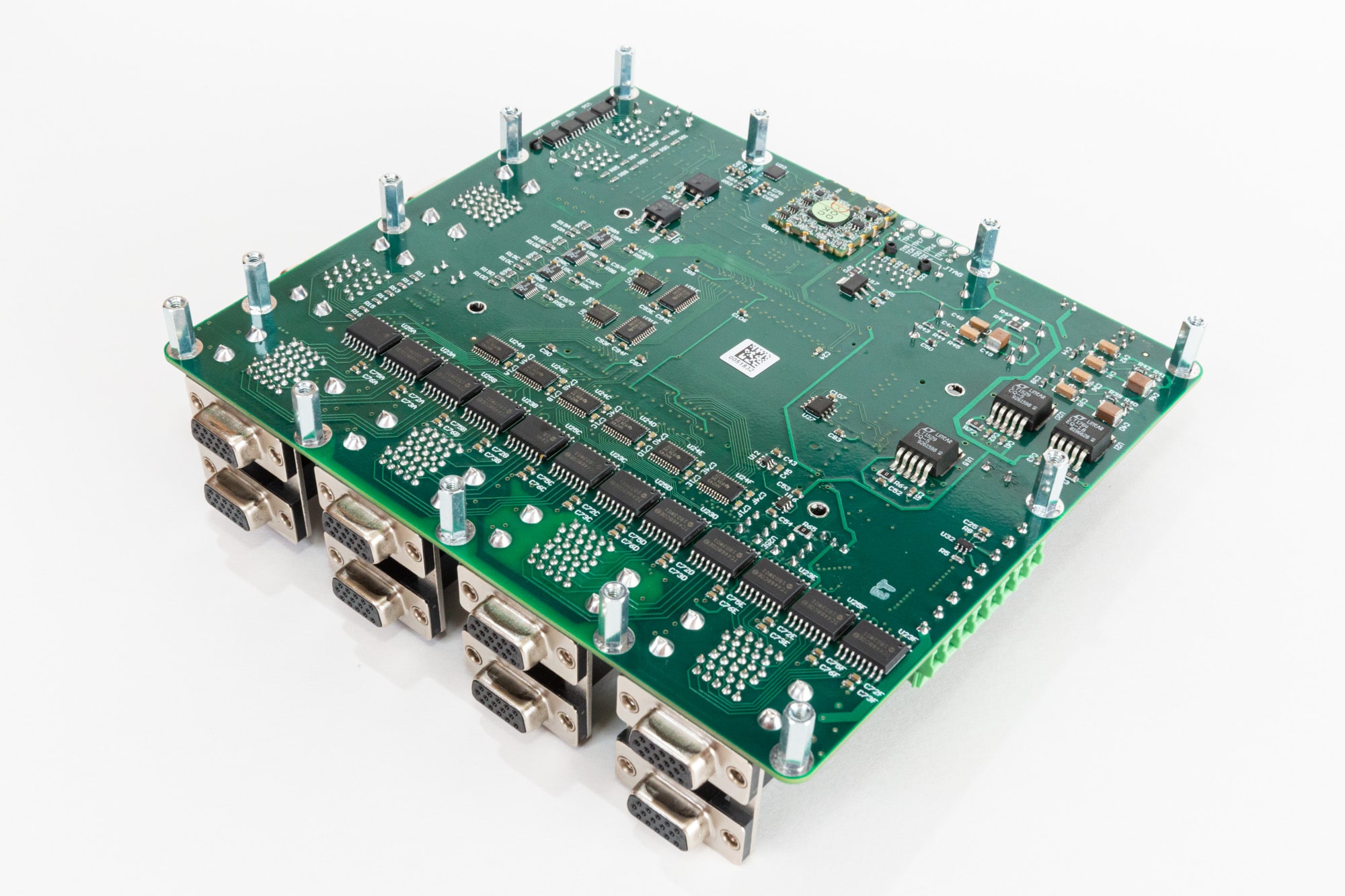
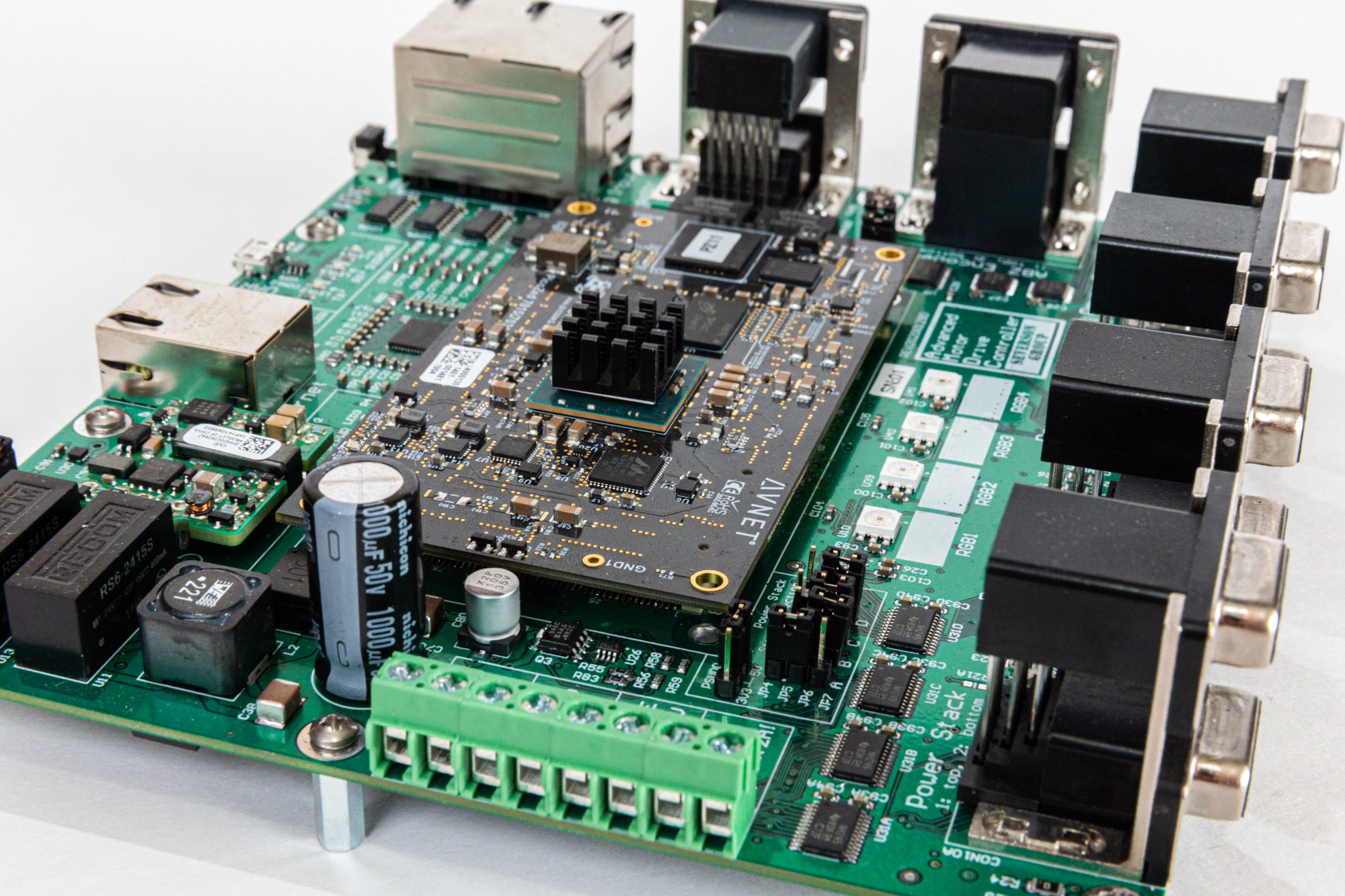
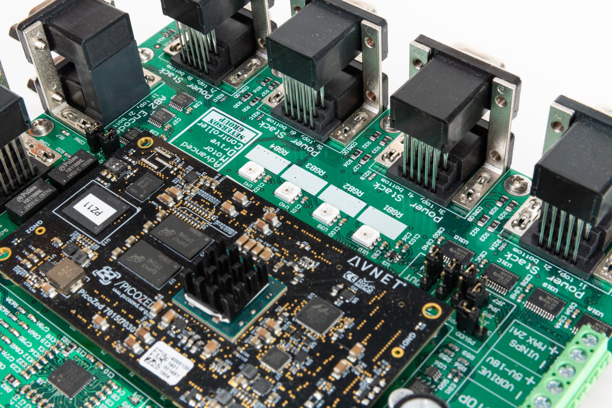
The fourth hardware design revision (REV D) of the Advanced Motor Drive Controller (AMDC) from the Severson Research Group marks a huge step improvement in quality of design, physical size reduction, and functionality compared to previous designs.
Background
About 2.5 years ago, I begin work on the Advanced Motor Drive Controller (AMDC), an open-source project designed for academic research in motor drives. Unbeknownst to me at the time, this project would end up taking me on a wild adventure through the most fun and rewarding experiences in my life thus far, leading me to where I am now!
The initial AMDC design experience (read about it here)…
- …led to interest in motors, power electronics, and control techniques
- …led to taking undergrad classes to learn about power engineering
- …led to being awarded prestigious power engineering award
- …led to applying for graduate studies at UW-Madison (in WEMPEC)
- …led to motor control project (funded by BETA Technologies)
- …led to working in VT at BETA Technologies as lead motor control engineer
- …led to funded development from BETA of next AMDC revision
- …led to coming back to UW-Madison for Ph.D. studies
- …led to studying advanced control techniques for bearingless motors
It’s kind of funny how a project can blossom into such rich experiences… Buried in this, there is a lesson to always look for new opportunities in life since you never know where they will take you. I sure am grateful for the opportunities I have been given.
Technical Details
The AMDC hardware design is based on the Xilinx Zynq-7000 architecture, a family of high-performance processors which tightly integrate FPGA fabric with dual-core digital signal processors. The user firmware then can access and control a plethora of peripherals designed for motor control applications (e.g. PWM outputs, analog inputs, encoder inputs, etc).
Most simple AC motor control applications require only a small subset of the I/O provided by the AMDC: 3x analog inputs (for current sensing feedback), 1x position sensor input (for rotor position feedback), and 6x PWM outputs (for driving a three-phase, two-level inverter).
However, the AMDC is not designed for simple control applications… It is designed for academic research into bearingless motor drives, where the control is significantly more complex and requires substantially more I/O and processing power. For example, a complete 6-DOF bearingless motor drive system might require up to 5x inverters (30x PWM outputs) and 16x analog inputs. The AMDC is designed to support these demanding requirements and more.
Open-Source Design
The entire AMDC platform has been open-source since its conception, with all hardware design files and software publicly available on GitHub for free usage.
Because of the amount of schematics for this design, I won’t go through them on this blog post, but instead, refer the reader to browse through them themselves — download them here.
GitHub Repositories
Hardware: https://github.com/Severson-Group/AMDC-Hardware/
Firmware: https://github.com/Severson-Group/AMDC-Firmware/
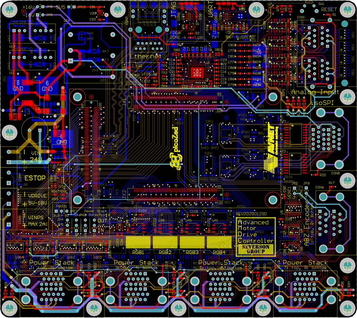
Pictures
