

OpenThermo: Customizable Thermostat for Furnace Control
Replace the old thermostat in your living space with a new fully customizable version that allows you to tweak the control algorithms used to keep the temperature comfortable.
This article details the design of a custom thermostat device for use in simple on/off furnace systems. It is called “OpenThermo” since it has been released as an open-source project (see the official GitHub project).
Introduction
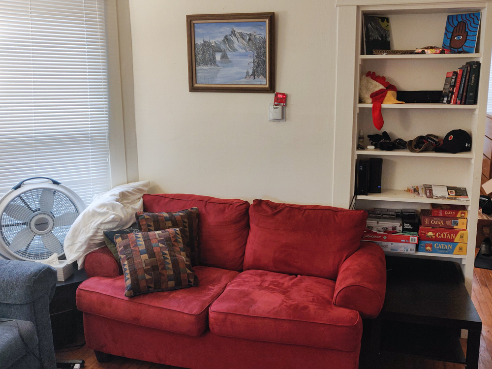
Each year of school at UW-Madison (after freshman year), I lived in an apartment near campus. I have managed to move every single year for five years straight! This year was no different. A small house became my new home this past August, into which I moved with a friend from the UW-Madison Men’s rowing team. We are sharing a cozy two bedroom flat in the two story house.
When the Wisconsin weather started getting chilly, we turned on the house’s heat. As the outdoor temperature fell day by day, we became increasingly aware of the lack of accurate indoor temperature control the wall thermostat provided. The heat definitely worked, but the wild hot/cold swings annoyed us. Eventually, we hit the breaking point. We took apart the built-in thermostat to figure out what was going on.
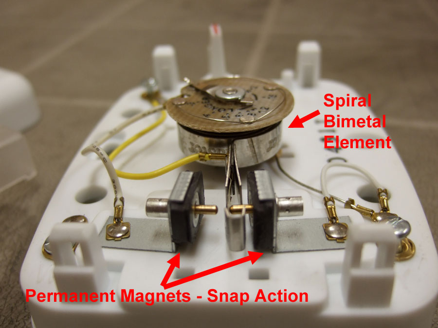
What we found inside surprised us: the thermostat was completely mechanical–no batteries or electronics at all. After some research, the unit is a Lux T10-1141SA Heating Only Thermostat, see datasheet. Reviews online indicate the thermostat is a reliable mechanical device with the main benefit of being battery-free. The device even has an “anticipator” (described later). Total cost of the unit from Amazon? $18.61.
Mechanical Thermostats
The core technology of the mechanical thermostat was invented in the 18th century and is based on the bimetallic strip. The bimetallic strip is actually two strips of different metals which are sandwiched together. Each metal has a different coefficient of thermal expansion which causes warping of the strip as the metal temperatures fluctuate. Commonly, the strip is formed into a coil so that temperature variation is transformed into rotary motion.
In the case of mechanical thermostats, this rotary motion is used to connect and disconnect a switch for the furnace. When the temperature falls, the coil contracts which causes the outer edge to make contact with the switch terminal, starting the furnace. As the ambient air temperature rises, the coil expands. Eventually, the spring action pulls it off the switch terminal, thus turning off the heat.
It should be noted that bimetallic strips form the backbone of many thermal control systems, not just home thermostats. For example, low-cost ovens rely on this technology to keep the temperature just right for the perfect bake.
These mechanical thermostats work well (and use no batteries!), but have several drawbacks:
- The temperature regulation band (i.e. +/- 1°F) depends on physical material properties and is hard to change.
- The set-point of the thermostat is not digital; there is no actual sensor which ensures the ambient temperature is at the desired level.
- Calibration is required to achieve acceptable operation.
How to fix these issues? Switch to a digital thermostat!
Digital Thermostats
To overcome the drawbacks of the venerable mechanical thermostat, a digital version can be used. These devices run on electricity and offer more customizable control of temperature. They typically have a temperature sensor, a display, and buttons or slider to set the desired temperature. For additional cost, more features can be added including programmability (i.e. change the temperature set-point at a certain time) and internet connectivity.
In the case of my house’s mechanical thermostat, the following commercially available alternatives offer equivalent functionality: single stage, heat only, non-programmable, digital display thermostats.
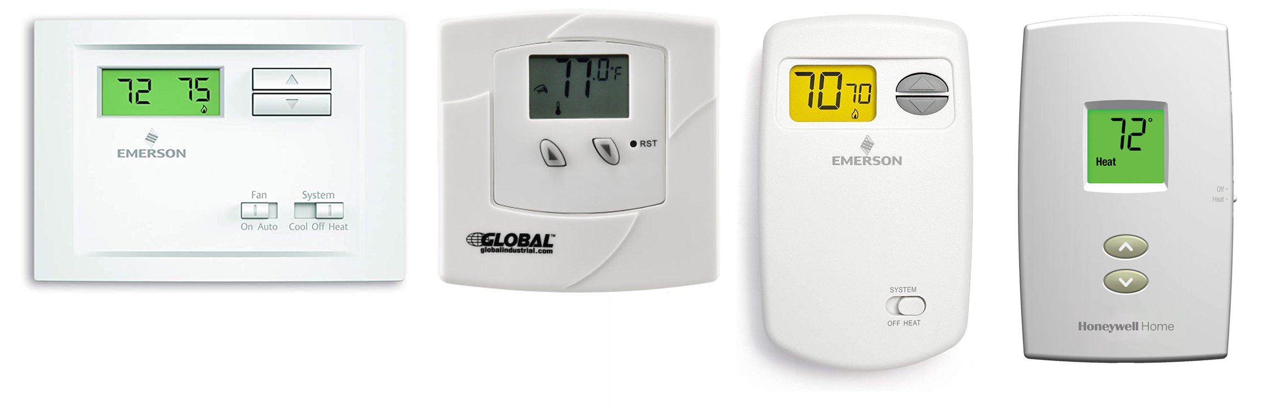
- $17.25 – Emerson NP110 Thermostat
- $17.50 – Global Industrial Thermostat
- $24.42 – Emerson 1E78-140 Thermostat
- $34.91 – Honeywell TH1100DV1000 Thermostat
These options are relatively cheap and generally perform well. They have thousands of five star reviews which indicate their satisfactory operation. However, the firmware cannot be updated and tailored to the unique application (e.g. temperature hysteresis band). Furthermore, without upgrading to an internet-connected device (which costs much more), data collection and heat usage statistics cannot be readily collected.
Enter the OpenThermo project.
OpenThermo Vision
The OpenThermo vision is to be a low-cost, customizable, digital thermostat. In principle, it directly replaces the above commercially available options. However, all source code and hardware is open-source and thus can be freely modified to better suit the target application. For example, compensation can be used to account for lag in the physical furnace. Additional statistics can be computed and displayed which are not usually offered by commercial variants (e.g. percent of time heat is on).
The remainder of this article details the design of the initial OpenThermo hardware platform and firmware.
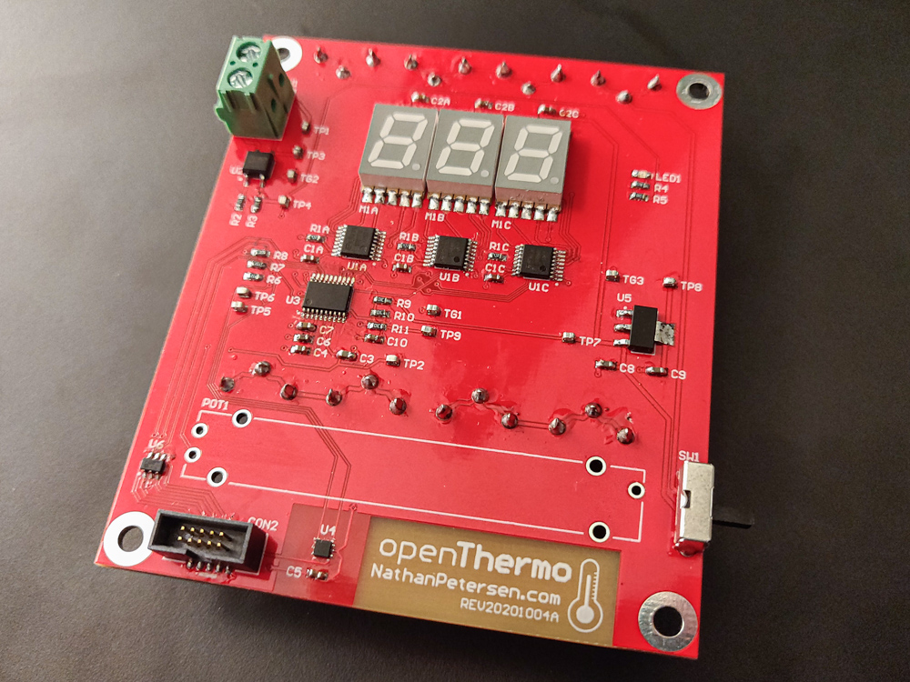
Hardware
The OpenThermo hardware circuit board design is composed of a collection of subsystems: microcontroller, temperature sensor, LED display, thermostat interface (optocoupler), slider. These systems work together to form the complete embedded system.
All the circuitry was custom designed in Altium Designer on a Saturday afternoon and ordered the next day.
See the full PDF of the schematics and PCB…
Circuit Design
Microcontroller
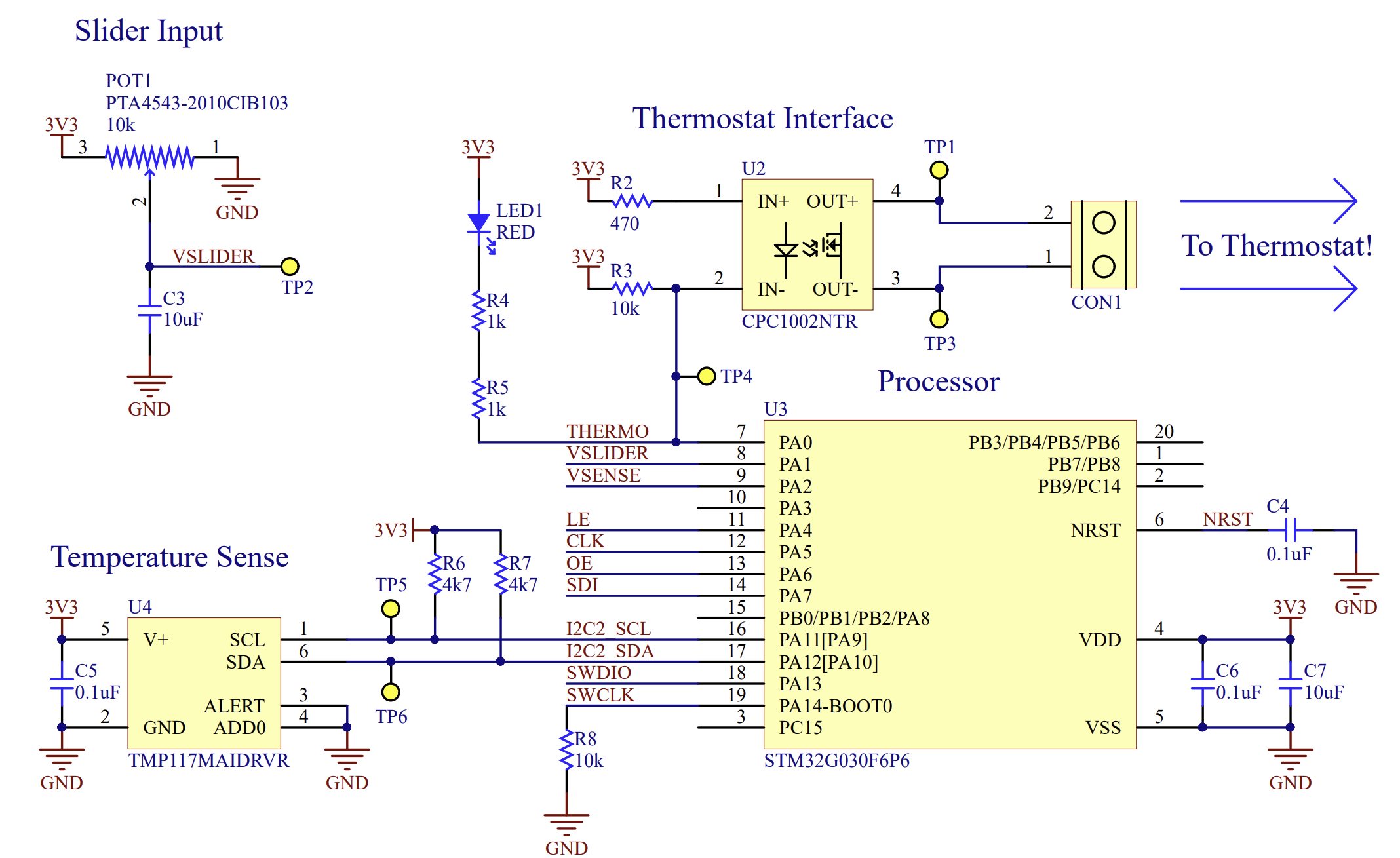
The core of the circuit design is the microcontroller which orchestrates the device functionality. Since I have previous experience with the STM32 product line, the STM32G030F6P6 was picked, see device U3 in the schematics. This is the cheapest 32-bit MCU available from ST, coming in at only $0.59 in quantity 5000 from Digi-Key. It features a Cortex-M0+ core operating up to 64 MHz. For this project, the minimal 20-pin TSSOP package variant was used. The device has minimal resources: 32KB of flash and 8KB of RAM. Furthermore, there is no floating point unit (FPU). This was deemed acceptable since the firmware required to control an on/off furnace is simple in nature.
Temperature Sensor
To sense the ambient temperature, a discrete temperature sensing device is needed. For this project, the TMP117 was selected for its very high accuracy: factory calibrated to +/- 0.1°C. This was one of the key benefits of designing custom hardware: accuracy and cost could be spent in the right places. I wanted to know the temperature very accurately, so using a multiple dollar sensor was worthwhile. The TMP117 sends updated temperature readings back to the MCU over I2C once every second. These are used as feedback for the closed-loop control algorithm. See device U4 in the schematics.
Furnace Interface
After a little tinkering with my house’s built-in mechanical thermostat, I found that the furnace could be controlled by simply connecting two wires together. Connecting the wires turned on the heat while disconnecting the wires stopped the heat.
The circuitry to do this is simple: an optoisolator (or optocoupler) is used as the switch to ensure no potential high-voltage spikes from the house furnace system can harm the circuitry. To the MCU, this switch appears as an LED, so it can be driven straight from one of the GPIO pins. The CPC1002N device is used in the design, see device U2 in the schematics.
User Interface (Display + Slider)
The user interface was kept minimal. Three 7-segment LED modules are used to show the current temperature, as well as the set-point and the percentage time the heat has been on. A potentiometer slider is used as the main interface for setting the temperature set-point. Finally, a single LED illuminates when the heat is on to visually show the device functionality.
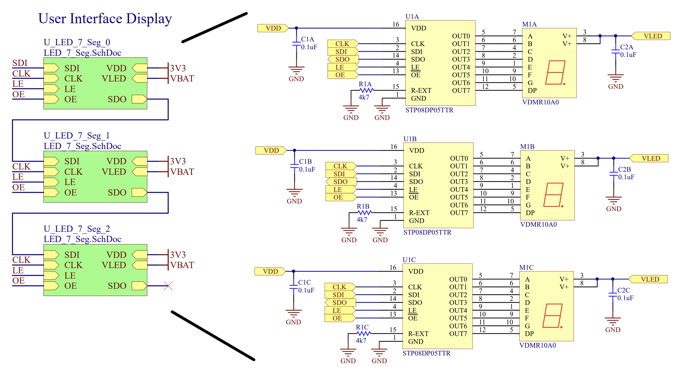
Each 7-segment LED module is operated using the STP08DP05, an eight-channel constant-current LED driver. These devices appear as a SPI-like device and can be daisy-chained to work like one big shift register. The 24 bits of output LED state are loaded into the devices using a serial interface composed of one clock and one data signal. Then, the latch signal is asserted so that the output mirrors the internal data. The LED drivers have an output enable pin which is used to control the brightness of the 7-segment modules using pulse-width modulation (PWM). Using this approach, all 24 LED segments (plus brightness) are controlled using four MCU pins.
The user adjusts the input slider to set the desired temperature. Fundamentally, when the user adjusts the input slider, the resistance of the potentiometer changes. This is used as a voltage divider to get a voltage output proportional to slider position. The internal ADC on the MCU is used to read this voltage and convert it to the desired temperature set-point for the control algorithm.
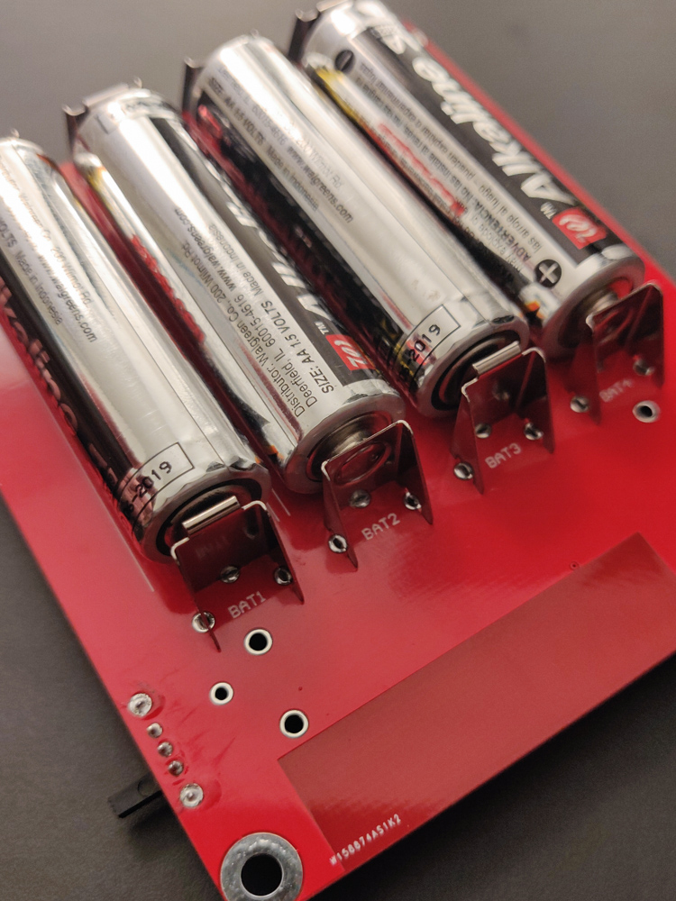
Power Supply
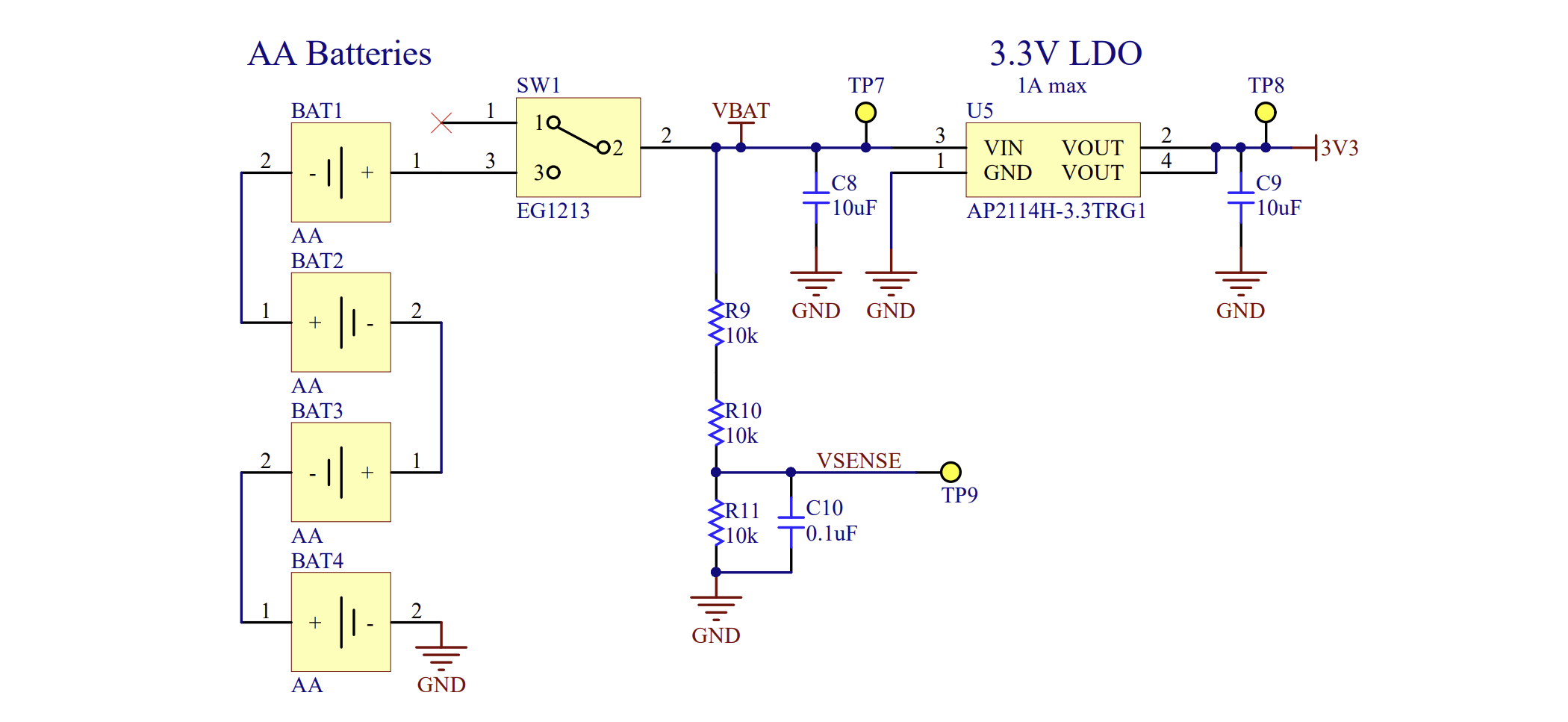
The device is powered via four AA batteries to form a 6V DC supply. The direct sum battery voltage is used by the LED drivers to power the 7-segment LED modules. A 3.3V low-dropout (LDO) regulator is used to power the MCU and temperature sensor. A scaled version of the battery voltage is provided to the MCU ADC for monitoring the batteries’ state of charge.
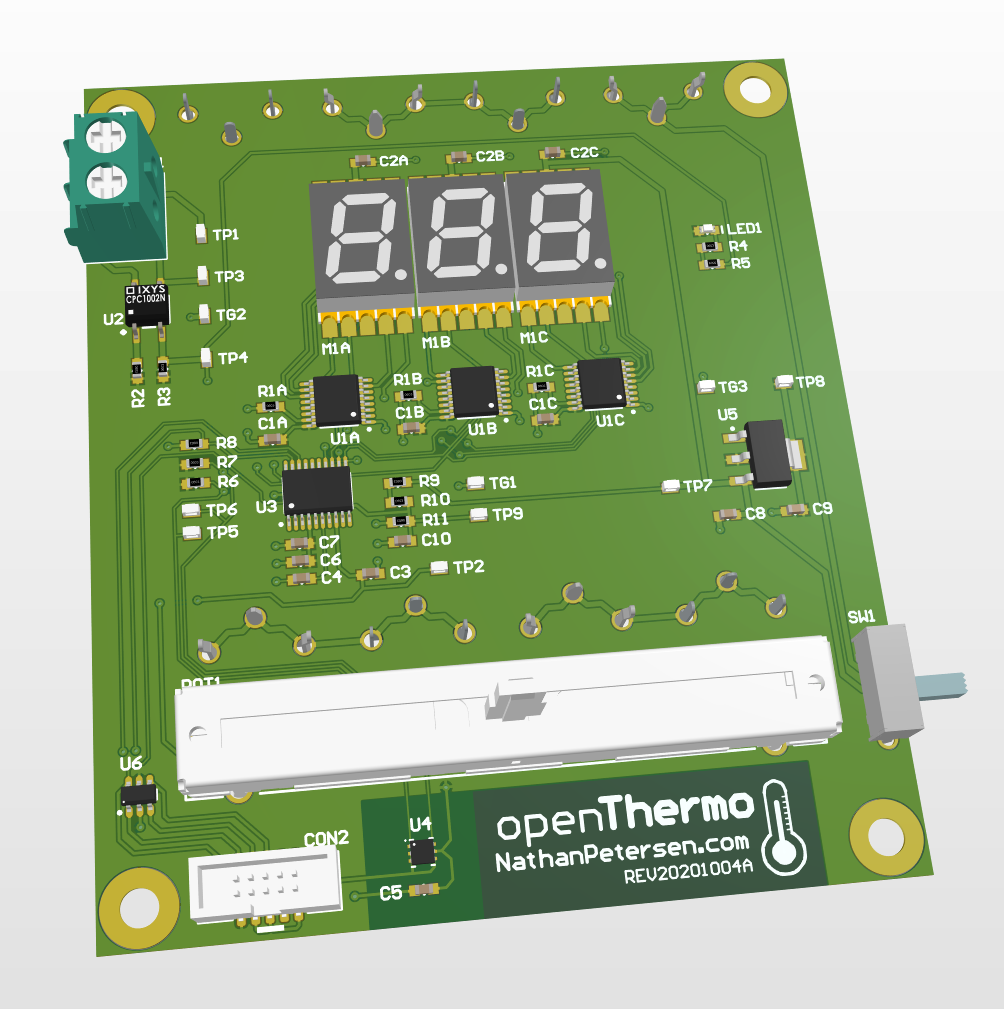
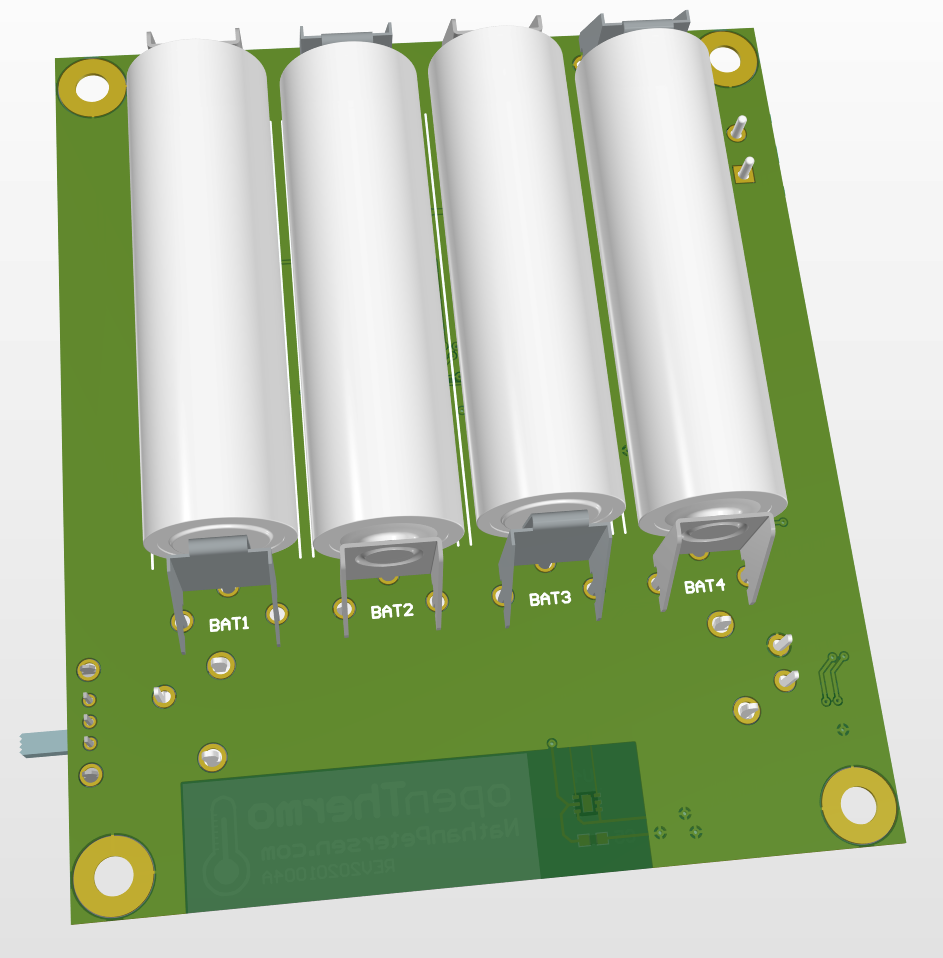
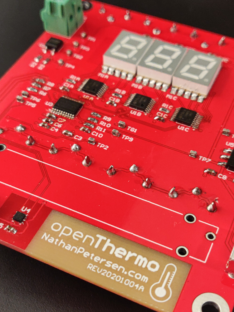
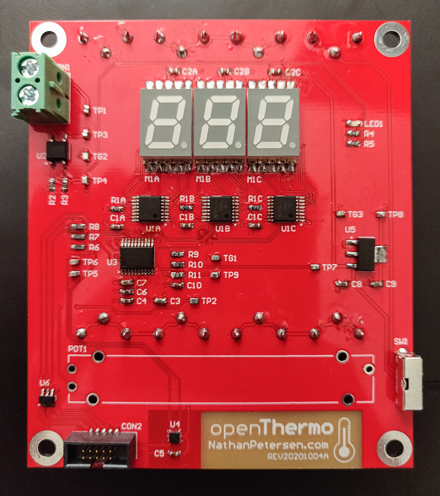
PCB Design
The OpenThermo PCB design was made to be the same footprint as the built-in mechanical thermostat in my house: 3” x 3.5”. The slider and LED display is on the front side, while the AA batteries take up the bulk of the back. All components are on the front for easy assembly. The temperature sensor is mounted away from other components so as to isolate it from heat sources. Finally, four mounting holes are provided in the corners for easy attachment.
See the complete Bill of Materials (BOM) for the OpenThermo…
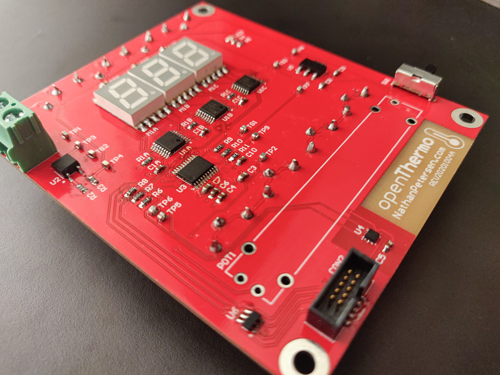
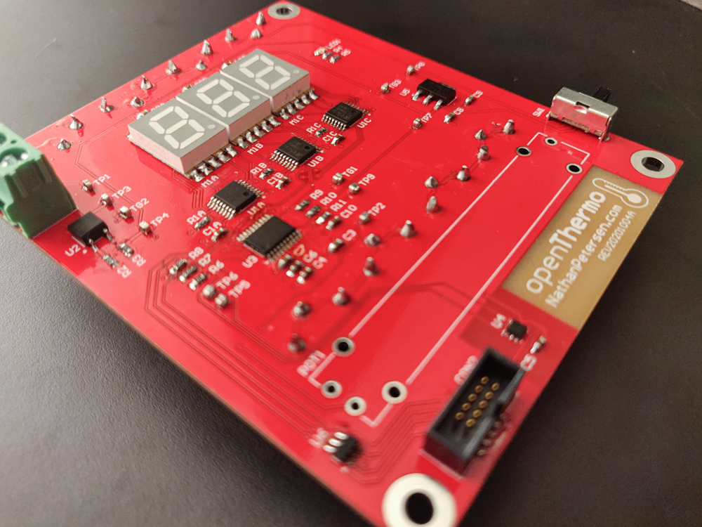
PCB Assembly
After completing the hardware design, I ordered the board blanks from PCBWay.com and waited for them to arrive. I also ordered the BOM for quantity 1 assembly from Digi-Key. In quantity 10, the BOM costs just under $21 per board from Digi-Key.
After everything arrived, I used my hot air rework station to put together the surface mount components and soldering iron to add the through hole devices. This went without issue as all footprints were the correct size.
Firmware
To bring the OpenThermo to life, embedded firmware is needed. For this project, custom bare-metal C code is used totaling just a few hundred lines. The complete firmware project can be found on GitHub. See the Src/ folder and the Inc/ folder for the main files.
General Structure
Since the firmware is fairly simple, a bare-metal approach is used (i.e. cooperative scheduling as opposed to a full blown preemptive RTOS). Nominally, the device is in sleep mode to save power. However, one peripheral timer is configured to run its interrupt service routine (ISR) every 100Hz. All device functionality executes within this ISR context.
The code is split into three main ideas:
- Drivers – low-level code which interface with hardware peripherals
- UI – responsible for maintaining the user interface
- Controller – handles the algorithm for when to turn on/off the furnace
The user interface updates at 100Hz (see the Src/ui.c file) and the controller runs at 1Hz (see the Src/controller.c file).
Temperature Control
The main point of a thermostat is to control the temperature. Since the output is a discrete binary state (i.e. furnace on or off), simple bang-bang control is all that can be used (as opposed to e.g. PID control).
Bang-bang control refers to the idea of the control output “banging” against the limits of output. In this case, that means furnace on or furnace off. To prevent damage to the furnace, hysteresis is typically added to limit the minimum cycle time. This requires that the output state (i.e. temperature) fluctuates within some band of the desired set-point.
To tune the performance of the hysteresis bang-bang controller, the upper and lower limits must be set in relation to the set-point value. This is typically defined as:
- The minimum output state value allowed before changing states
- The maximum output state value allowed before changing states
In the case of the thermostat, this is typically defined as a hysteresis band: e.g. +0.1°F / -0.5°F. This results in a trade-off between furnace cycle time and temperature fluctuations. The tighter the tolerance in fluctuation (e.g. +/- 0.1°F), the more rapid the furnace turns on and off.
UI Management
The UI has three states:
- Boot – Displays the welcome screen while the system initializes
- Set-Point – Displays the set-point from the slider input
- Control – Displays the temperature and the percentage of heat on time
When the slider is moved, the UI state is updated to display the set-point temperature value. After five seconds of idle slider movement, the set-point is locked in and the device moves to its nominal UI mode. In this nominal mode, the display alternates every 10 seconds between the current ambient temperature and the percentage of heat on time.
The goal of the UI management code is to provide a dynamic and fluid user experience. This requires that the 7-segment LED display changes right away when the slider is moved, and that small ambient temperature changes are reflected on the display right away. This is achieved via careful firmware design using quantization and low-pass filters.
Since the temperature state itself is discrete, some clever firmware is needed to make the device appear responsive. The TMP117 temperature sensor device is configured on boot to sample the temperature asynchronously at its maximum rate of 1Hz. This means that the OpenThermo display could only update with new data at 1Hz–not fast enough! To solve this, a discrete-time low pass filter (LPF) is used to trick the user into thinking that the temperature estimate updates at 100Hz. The bandwidth of the filter is set to 0.1Hz.
The output of the slider (from the internal MCU ADC) is also filtered with a 2Hz bandwidth. This provides a satisfying smoothing effect when the set-point is changed. On top of this, the output from the slider is quantized to integer values before the LPF. Even though the slider itself is a continuous input, the displayed set-point “locks” into the integer values (e.g. 70°F, 71°F, etc).
The combination of all this results in a satisfying user experience.
Low-Pass Filter
The firmware uses low-pass filters (LPF) on nearly all signals, all of which are tuned to different bandwidths. Some operate at the UI update rate of 100Hz and others at the control rate of 1Hz. This merits some discussion on how they work and how to design them.
All filters in the code implement simple, first-order infinite impulse response (IIR) low-pass filters (LPF). The difference equation for the filter is given by
$$ y[k] = A y[k-1] + x[k] (1-A) $$
where $ A = \exp(-2 \pi f_b T) $, $T$ is the sample rate, and $f_b$ is the desired bandwidth in Hz. Intuition tells us that this difference equation makes sense: for each output time step, this takes a portion of the previous output and (1-portion) of the current input. Thus, the closer to 1.0 the constant $A$ becomes, the slower the response.
Converting the difference equation to the z-domain results in the following transfer function
$$ \frac{Y(z)}{X(z)} = \frac{1-A}{1-Az^{-1}}. $$
When the sample time $T = 1$ second and $1/f_b = 4$ hours, then $A = 0.9996$ and the following is the filter step response to unit step input.

Filter step response to unit step input.
This same filter is used to convert the pulse-width modulated furnace on signal into the percent of heat on time. In the firmware, the on signal is a simple step function between 0 and 100. This is filtered using the above difference equation and tuning. The resulting waveforms are shown below when the furnace cycle time is 15 minutes and the duty ratio is 35%.

Filtered percent heat on resulting from low-pass filter.
Notice that in steady-state, the output fluctuation is about +/- 5%. Furthermore, it takes the filter about 2 hours to stabilize the output to the given input.
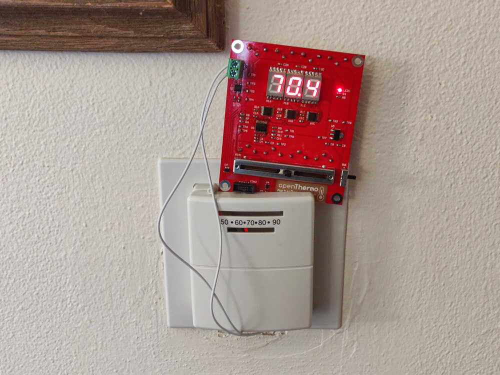
Results
This project took the fairly simple idea of a thermostat and did the engineering work required to create a useable tool for my home. This is the first electronics project I have done that resulted in real value for me and others (my roommate)–something that I actually use daily and improves my life. Neither my Razzler project nor the Gradled project did this… :)
It is very satisfying to hear the heat turn on knowing that my pile of hardware and firmware is at work! Tuning the control algorithm (i.e. setting the temperature hysteresis band limits) took a few code iterations, but this was minor.
In the end, OpenThermo achieves +0.1°F / -0.5°F temperature regulation with furnace cycles lasting about 10-15 minutes (i.e. 4-6 cycles per hour). This isn’t really a direct result of the project, but more reflects the furnace and insulation quality of my home.
After using OpenThermo for a while, I found that the percentage of heat on time is about 20% to 40%, depending on:
- outdoor temperature
- thermostat set-point
- home influences (e.g. oven, door open, etc).
Obviously, the percentage of heat on time is related to the insulation efficiency of the home. I noticed that small changes in set-point resulted in large changes in percent heat on. This prompted me to run an experiment to try and characterize the home insulation effectiveness. In this experiment, I initially cooled off the house. Then, the heat turned on full blast and I recorded the temperature for 45 minutes. The resulting plot is shown below. Interestingly, saturation occurred around 70°F. This helps inform smart thermostat usage by putting the set-point in an efficient zone: at or below 70°F.

45 minutes of continuous heat on. Outdoor weather: 31°F, 3 mph winds.
Updates After Winter
Updated May 18, 2021
After designing and building OpenThermo last Fall 2020 and installing into my home, I have been observing its operation daily for the past six months during the winter season. Here in Madison, WI, it gets pretty cold – typically down to around -20F (-30C) on the coldest mornings. Since OpenThermo displays the percent of time the heat has been on, it has been very interesting to compare the percent to the outdoor temperature, as well as other events happening in the house.
My key findings (fairly obvious):
- The outdoor temperature significantly impacts the percent heat on
- The temperature set point (e.g. 70F vs 68F) hardly impacts percent heat on
- Due to the relatively small size of my house (i.e., less than 1000 ft²), the thermostat is greatly influenced by things in the house (e.g., open windows, doors, oven, space heaters)
- Using the oven significantly affects the percent heat on – it can cause the thermostat to stay off for hours, depending on the outdoor temperature
Note that the above findings are outside the scope of OpenThermo; any responsive thermostat would behave like this. The key advantage of OpenThermo is that it displays the heat on percentage in real-time.
Outdoor Temperature vs. Heat On Percentage
Since the outdoor temperature seemed to have the most significant impact on the heat on percentage, I decided to collect data to observe the trend in more detail. For many months throughout the winter, each morning, I wrote down the outdoor temperature and the heat on percentage. The set-point was always at 70F. I only recorded data on the “normal” days when the oven hadn’t been on and the sun hadn’t been up for too long. Ideally, I recorded the data at 7am to 8am after just waking up. Since the heat on percentage bounces around due to the low-pass filtering (see above section), I always recorded the maximum value, right after the heat turned off. Below is the final plot of the data:

Daily data relating outdoor temperature to heat on percentage. Linear curve fit and 95% prediction interval are shown.
An interesting trends emerges! The data effectively trends linearly (R² value is close to 1), meaning that there is a direct relation between outdoor temperature and heat on percent. At 0% heat on, the expected outdoor temperature is between 55F and 70F – this agrees fairly well to the set-point of 70F. At 100% heat on, the outdoor temperature is between -20F and -40F – this means that the furnace would not be able to heat the house if it got colder than this range. Overall, it is clear that the percent heat on acts as a fairly good proxy for the outdoor temperature: for example, when it reads 50%, we can expect temperatures between 10F and 30F.
The plot can also be used to predict furnace failures near the 100% mark. Not surprisingly, the house furnace broke in the middle of winter one morning when the outdoor temperature was -25F. Based on the plot, this would map to a heat on percent of nearly 100%! The furnace simply could not survive running constantly.
Summary
Well, in summary, it works. This project was fun but not terribly challenging. I ended up fully designing and ordering the hardware in less than 24 hours and finishing the firmware in an afternoon. However, I am pleased with the results!
After using and thinking about the OpenThermo project for a while, I conclude that any sane person would have just purchased a cheap commercial version from the previous list in this article, rather than design and build a thermostat from scratch.
However, I do believe that the OpenThermo project has a place in this world: customizable thermostat for data collection. I am very interested in collecting data and making plots to evaluate the heating capabilities of my house. Specifically, I want to experimentally find the ideal temperature set-point as a function of the outdoor temperature. To do this, I need data. Lots of data.
This gives the OpenThermo project a reason to live on! The next version will focus on data collection and customizability.
Future Plans
I plan on designing v2 of the OpenThermo hardware and firmware. Here’s the potential list of changes:
- 8 character (14-segment per character) LCD display
- Non-volatile memory stores configuration data
- SD card to log temperature data
- Extra buttons for changing modes, etc
- Real-time clock for time-based programable temperature set-point
Pictures
New Post Notifications
If you read this far, you might be interested in subscribing for email notifications about future new posts I write. I will never spam you! Every few months, I write a new article for this website, and will send you email about it. You can unsubscribe at any time. Thank you.